Reactor actuation area for traveling wave reactor and manufacturing method for reactor actuation area of traveling wave reactor

A manufacturing method and technology of traveling wave reactor, which are applied in the direction of reactor, control of nuclear reaction, reduction of greenhouse gases, etc., can solve the problems such as no design plan for the starting area of ​​traveling wave reactor, reactivity fluctuation, etc., so as to avoid reactivity fluctuation, The effect of improving safety

Active Publication Date: 2014-09-24
NUCLEAR POWER INSTITUTE OF CHINA
View PDF10 Cites 5 Cited by
  • Summary
  • Abstract
  • Description
  • Claims
  • Application Information

AI Technical Summary

Problems solved by technology

This article gives the relevant design direction from the perspective of empirical analysis, but does not give a specific design plan for the start-up area of ​​the TWR
[0004] In addition, the usual TWR start-up area will cause long-term and severe reactivity fluctuations in the start-up process

Method used


Image

  • Reactor actuation area for traveling wave reactor and manufacturing method for reactor actuation area of traveling wave reactor
  • Reactor actuation area for traveling wave reactor and manufacturing method for reactor actuation area of traveling wave reactor
  • Reactor actuation area for traveling wave reactor and manufacturing method for reactor actuation area of traveling wave reactor

Examples


Embodiment 1

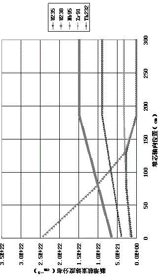
[0057] TWR start-up area, including fertile nuclides, fissile nuclides and simulated nuclides;

[0058] Along the direction from the front end of the start-up area to the new fuel area, the concentration of convertible nuclides gradually increases, and the concentration of convertible nuclides at the rear end of the start-up area is the same as that in the new fuel area;

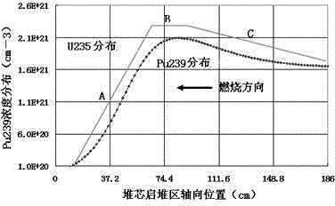
[0059] Along the direction from the front end of the start-up area to the burning area, the shape of the concentration distribution curve of fissile nuclides in the start-up area and the fissile nuclides produced at that point when the propagation wave and incineration wave in the burning area pass through a certain point in sequence. The shape of the concentration change curve of the element corresponds to;

[0060] Along the direction from the front end of the start-up area to the new fuel area, the concentration of the simulated nuclide gradually decreases, and the concentration of the simulated nuclide a...

Embodiment 2

[0089] This embodiment provides a manufacturing method of the TWR start-up region as shown in Embodiment 1.

[0090] The method includes the following steps:

[0091] Initial parameter preset steps:

[0092] Along the direction from the front end of the start-up area to the new fuel area, the concentration distribution curve of fissile nuclides is divided into a gradually rising straight line segment C, a horizontal straight line segment B and a gradually falling straight line segment A

[0093] Determine the total length of the start-up area, determine the proportion of section A in the total axial length of the start-up area, determine the concentration of fissile nuclides in section B, determine the length of section B, and determine the fissile nuclei at the beginning of section C concentration of toxin;

[0094] According to the formula Calculate the concentration of other nuclides at each point in the start-up area, and obtain the concentration marking line of each n...


PUM


Abstract

The invention discloses a reactor actuation area for a traveling wave reactor. The reactor actuation area comprises fertile nuclides, fissile nuclides and simulated nuclides, wherein the concentration of the fertile nuclides is gradually increased along a direction from the front end part of the reactor actuation area to a novel fuel area, and the concentration of the fertile nuclides at the rear end of the reactor actuation area is the same as that of the fertile nuclides in the novel fuel area; along a direction from the front end part of the reactor actuation area to a combustion area, the shape of a concentration distribution curve of the fissile nuclides in the reactor actuation area corresponds to that of a concentration variation curve of the fissile nuclides at a certain point when breeding waves and combustion waves in the combustion area sequentially pass through the point in the combustion area; the concentration of the simulated nuclides is gradually decreased along a direction from the front end part of the reactor actuation area to the novel fuel area. The reactor actuation area has the advantages that the requirements of actuation of the traveling wave reactor for running are met, the production of reactive fluctuation is avoided, and the safety, economy and controllability of the reactor are improved. The invention also discloses a manufacturing method for the reactor actuation area.

Description

technical field [0001] The invention relates to the field of nuclear industry, in particular to a traveling wave reactor, in particular to a start-up area of ​​a fuel core body of a traveling wave reactor. Background technique [0002] A TWR (traveling wave reactor) differs from other types of reactors primarily in the way it burns fuel. It first converts the fertile nuclides into fissile nuclides, and then burns the new fissile nuclides produced in situ. This method is called "value-added-incineration" in the research. It can reduce or even eliminate aftertreatment, refueling and other auxiliary processing processes, ensuring the sustainable development of nuclear energy, and at the same time has extremely high economy and safety. [0003] In the article "Sekimoto H, Miyashita S. Startup of CANDLE burnup in fast reactor from enriched uranium core. Energy Conv Manag 2006;47:2772–80." published by Professor Sekimoto Hiroshi, Tokyo Institute of Technology, the traveling wave ...

Claims


Application Information

Patent Timeline
Patent Type & Authority Applications(China)
IPC IPC(8): G21C7/00
CPCY02E30/40Y02E30/30
Inventor 严明宇孙伟李庆
Owner NUCLEAR POWER INSTITUTE OF CHINA
Why Eureka
Try Eureka