Integral residual current circuit breaker

A leakage circuit breaker, integrated technology, applied in the direction of circuit breaker components, circuits, electrical components, etc., can solve the problems of inconvenient assembly, inability to disassemble and adjust, and unreasonable structural layout of leakage circuit breakers, so as to achieve firm fixation of pins Reliable, compact and inexpensive design effect

Active Publication Date: 2014-09-24
ZHEJIANG CHUANGQI ELECTRICAL CO LTD
View PDF6 Cites 8 Cited by
  • Summary
  • Abstract
  • Description
  • Claims
  • Application Information

AI Technical Summary

Problems solved by technology

However, its structural layout is unreasonable, and the position adjustment structure of the bimetal sheet in the thermal tripping system has not been improved. One end of the screw corresponds to the bimetal, and pushes and cooperates with the bimetal, and the other end of the adjusting screw is the operating end; The fine-tuning of the screws not only brings inconvenience to the assembly of the leakage circuit breaker; once the position of the bimetallic sheet deviates greatly, it cannot be adjusted by the adjusting screw, and the shell needs to be disassembled to adjust the position of the bimetallic sheet, which causes inconvenience to the adjustment operation, especially It is more difficult to disassemble when there are multiple L pole parts; and after the leakage circuit breaker has been used for a long time, the bimetal sheet has problems such as solidification in position and insensitive action, so it is necessary to disassemble the casing and push the bimetal sheet Adjustment operation, and once the shell is disassembled during use, it is easy to cause damage to the internal components, which will bring serious problems to the use of the leakage circuit breaker, and in serious cases, it will not be able to be used, and in the case of multiple L poles, it cannot be performed at all. Disassembly and adjustment, so existing users usually use direct replacement, which cannot be repaired, resulting in a waste of resources

Method used


Image

  • Integral residual current circuit breaker
  • Integral residual current circuit breaker
  • Integral residual current circuit breaker

Examples


Embodiment Construction

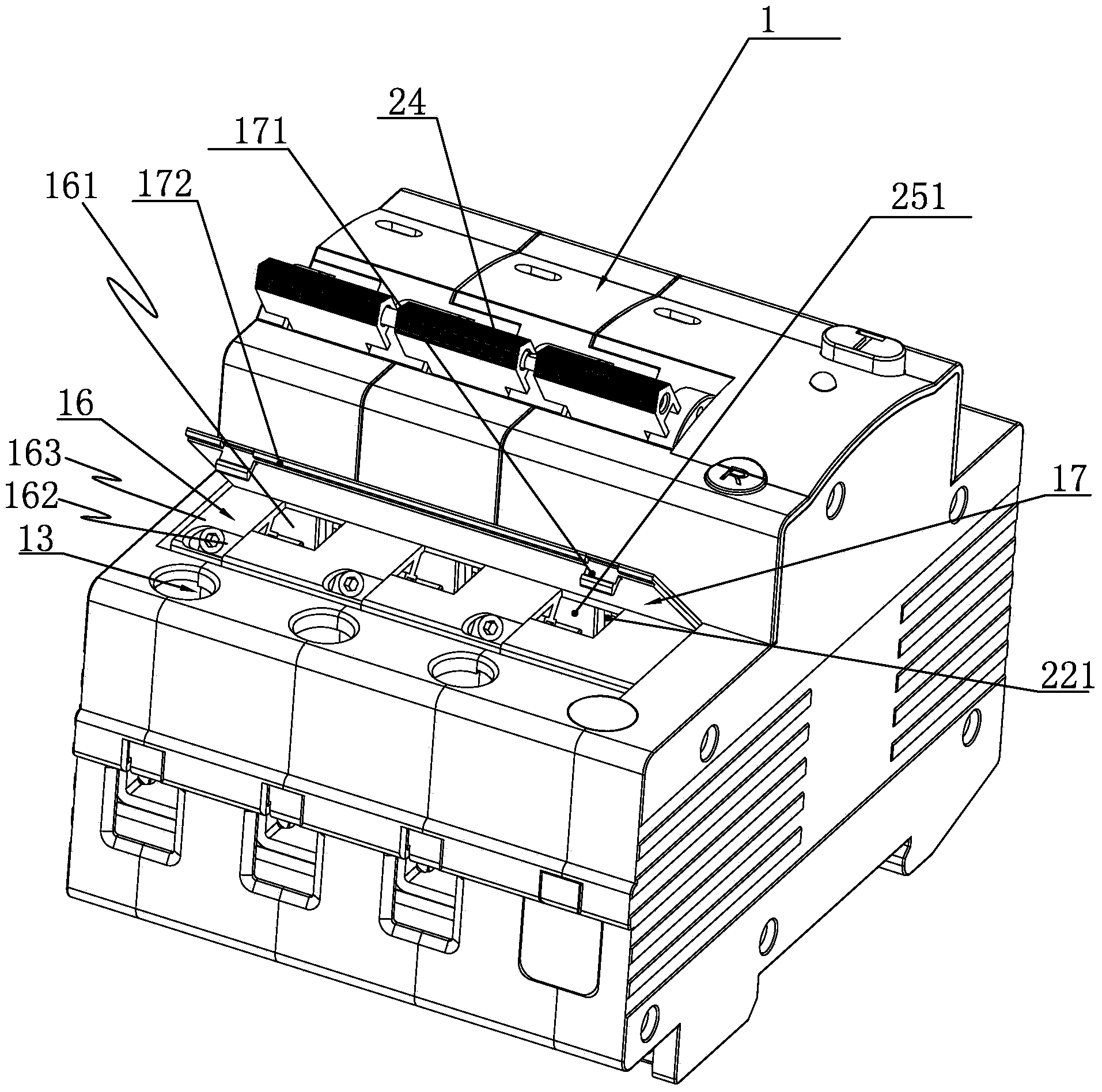
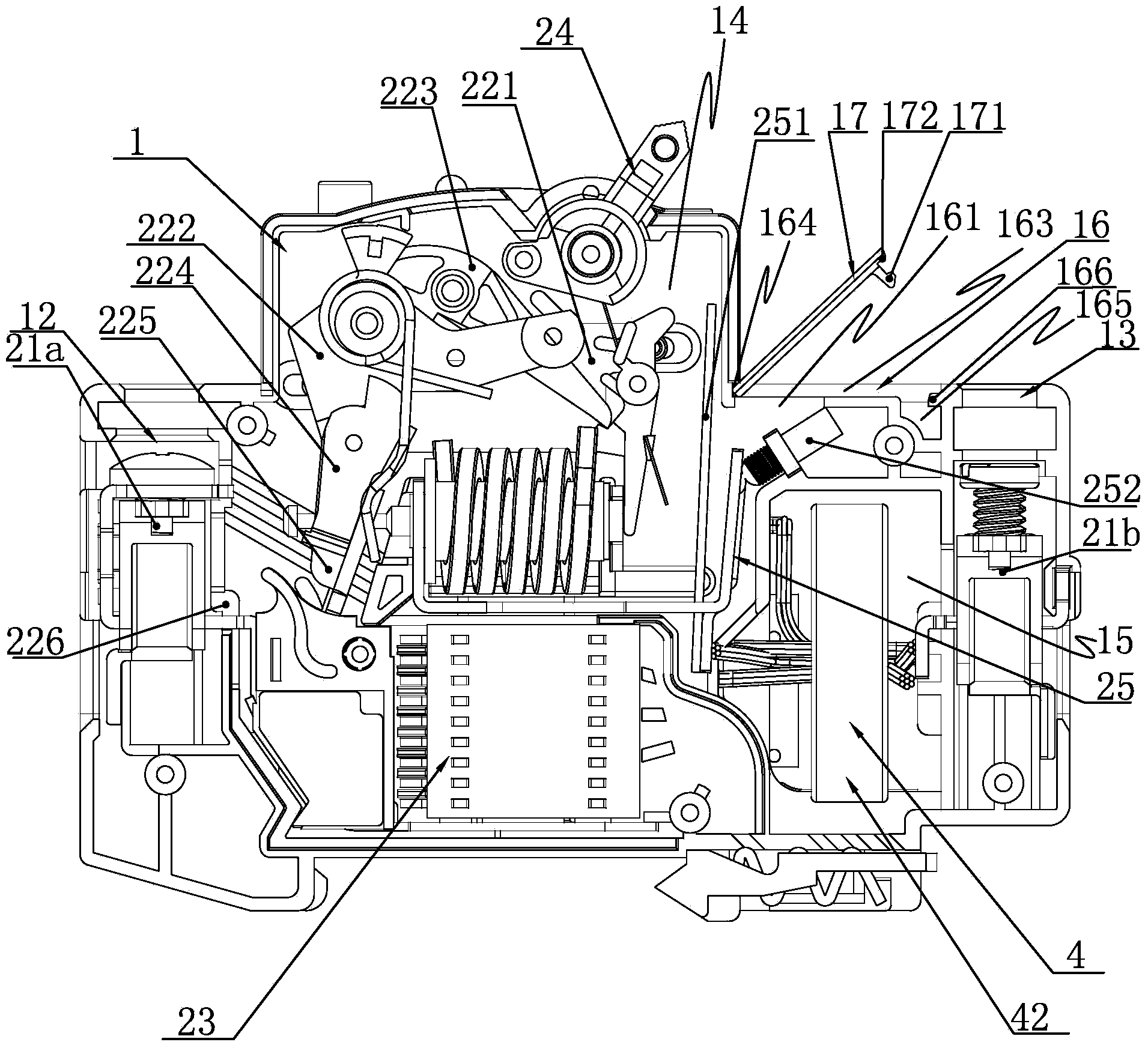
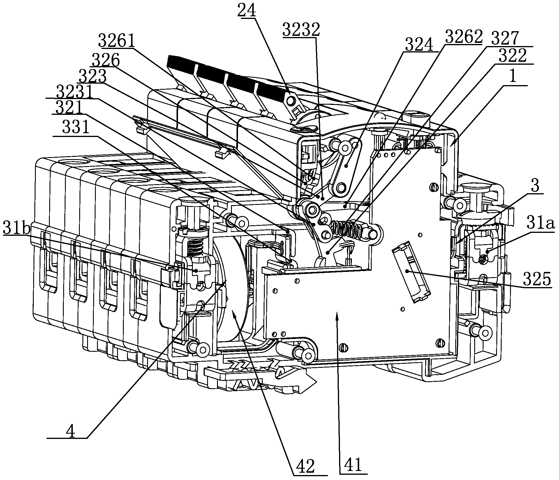
[0036] See attached figure 1 to attach Figure 10 , an integral earth leakage circuit breaker disclosed by the present invention includes a casing 1, and an N pole part 3 assembled in the casing 1, a leakage detection part 4 and at least one L pole part 2; wherein the leakage detection part 4 includes Circuit board 41 and current transformer 42, it is well-known technology well known to those skilled in the art; Described N pole part 3 includes N pole inlet and outlet wiring terminals 31a, 31b, and the wires connected on N pole outlet terminal 31b Through the transformer 42 of the leakage detection part 4; the L pole part 2 includes L pole incoming and outgoing line terminals 21a, 21b, and an L pole electromagnetic tripping device connected between the L pole incoming and outgoing line terminals 21a, 21b 22. The L-pole arc extinguishing device 23, the double gold system 25, the L-pole electromagnetic tripping device 22 is connected with the operating handle 24; the L-pole ele...


PUM


Abstract

The invention relates to an integral residual current circuit breaker. A transformer placing cavity for placing a transformer of a residual current detection part is arranged in a position, between an assembly cavity and an outlet terminal mounting seat, on a shell. A bimetal sheet adjustment platform is formed above the transformer placing cavity of the shell. The bimetal sheet adjustment platform is provided with an observation window and an adjustment window. The observation window passes through the bimetal sheet adjustment platform. The observation window corresponds to a position of matching between a bimetal sheet and a lock catch in an L-pole electromagnetic tripping device. An adjustment screw is installed in the adjustment window. The adjustment platform is covered with a sealing cover. Compared with the prior art, the integral residual current circuit breaker has the advantages of compact structure, convenient and reliable bimetal sheet position adjustment operation, easy installation, and easy bimetal sheet adjustment and repair.

Description

technical field [0001] The invention relates to a circuit breaker, in particular to an earth leakage circuit breaker, in particular to an integral leakage circuit breaker. Background technique [0002] Traditionally, in order to realize the two protection functions of overvoltage and leakage, the manufacturers of circuit breakers adopt the assembly type of overvoltage release, leakage release and circuit breaker. This type of implementation will take up a lot of space in the cabinet, secondly, it will make the wiring method very complicated, thirdly, it will increase various costs, and fourthly, it will consume materials and waste resources, so it is not practical. [0003] In order to solve the above technical problems, Beijing Bodun Electric Co., Ltd. designed and applied for the "Overvoltage Protection Type Leakage Circuit Breaker with a Width of 36mm" (authorized announcement number is CN 202230964 U), its main structure is: including the L pole part and the N pole part....

Claims


Application Information

Patent Timeline
Patent Type & Authority Applications(China)
IPC IPC(8): H01H71/40H01H71/02H01H73/18
Inventor 沈玉文戴安彩吴和锋张雪
Owner ZHEJIANG CHUANGQI ELECTRICAL CO LTD
Why Eureka
Try Eureka