Method and control device for charging or discharging a piezoelectric actuator

A technology for actuators and control devices, which is applied to components of piezoelectric devices or electrostrictive devices, electrical control, engine control, etc., can solve problems such as limitations, and achieve high accuracy and short control time Effect

Active Publication Date: 2017-06-09
ROBERT BOSCH GMBH
View PDF1 Cites 0 Cited by
  • Summary
  • Abstract
  • Description
  • Claims
  • Application Information

AI Technical Summary

Problems solved by technology

However, the known method only achieves a limited degree of accuracy with respect to charging or discharging of the piezoelectric actuator, especially in the case of relatively temporary actuation of the piezoelectric actuator.

Method used


Image

  • Method and control device for charging or discharging a piezoelectric actuator
  • Method and control device for charging or discharging a piezoelectric actuator
  • Method and control device for charging or discharging a piezoelectric actuator

Examples


Embodiment Construction

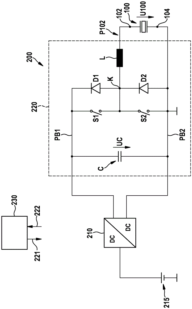
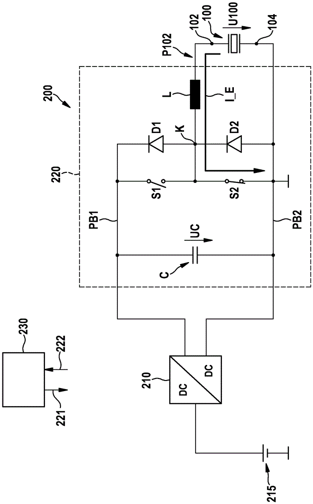
[0029] figure 1Circuit system 220 of actuation device 200 for a piezoelectric actuator 100 is shown. The actuating device 200 has a DC (direct current) / DC converter 210 which generates an output DC voltage from a DC voltage supplied to it from an input side via a voltage source 215 (for example, a motor vehicle body network battery). The DC voltage is, for example, greater than the input voltage of the voltage source 215 . Here, the output voltage of the DC / DC converter 210 is about 200 volts, for example.

[0030] Buffer capacitor C of circuit system 220 of actuating device 200 is charged via DC / DC converter 210 to the output voltage of DC / DC converter 210 . The voltage applied to buffer capacitor C is designated here with the reference symbol UC. due to figure 1 The lower interface of the buffer capacitor C is directly connected to a common ground potential, which corresponds to a second reference potential PB2, so the voltage UC on the buffer capacitor C corresponds to ...


PUM


Abstract

The invention relates to a method for charging or discharging a piezoelectric actuator (100), in particular a piezoelectric actuator of an injection valve of an internal combustion engine, wherein a first part of the actuator (100) An interface (102) is at least temporarily placed via a transfer inductance (L) at a first reference potential (PB1), characterized in that the actuator (100) is actuated according to the first reference potential (PB1 ) and the potential difference between the potential (P102) on the first interface (102) of the actuator (100).

Description

technical field [0001] The invention relates to a method for charging or discharging a piezoelectric actuator, in particular of an injection valve of an internal combustion engine, wherein a first interface of the actuator is at least temporarily via a The transfer inductance is placed at a first reference potential. [0002] The invention also relates to a control device for carrying out such a method. Background technique [0003] A method and an actuation device for charging or discharging a piezoelectric actuator are known from EP 1 139 448 B1. However, the known method only achieves a limited degree of accuracy with respect to charging or discharging of the piezo-actuator, especially in the case of relatively temporary actuation of the piezo-actuator. In particular, variables that change during the operation of the actuation device or the actuator are not taken into account sufficiently. Contents of the invention [0004] It is therefore the object of the present i...

Claims


Application Information

Patent Timeline
Patent Type & Authority Patents(China)
IPC IPC(8): F02D41/20H01L41/04
CPCF02D41/2096F02D2041/2003F02D2041/201F02D2041/2058H10N30/802
Inventor J-H.巴特M.克里格B.奥斯滕多夫M.格拉夫
Owner ROBERT BOSCH GMBH
Why Eureka
Try Eureka