Excess temperature detection method and fluid control equipment in tubing soldering

A technology for controlling equipment and fluids, applied in welding equipment, metal processing equipment, manufacturing tools, etc., can solve the problems of labor and time required for temperature detection, failure to detect heat transfer, heat transfer to the inside of the main body, etc.

Inactive Publication Date: 2014-10-01
SAGINOMIYA SEISAKUSHO INC
View PDF4 Cites 0 Cited by
  • Summary
  • Abstract
  • Description
  • Claims
  • Application Information

AI Technical Summary

Problems solved by technology

In this brazing operation, the main body of the valve unit is usually cooled, however, there may be cases where heat is transferred to the inside of the main body through the joint due to some malfunction.
[0010] However, in the case where heat transfer occurs in a part of the joint, as far as the method of using the temperature-indicating member or the temperature-indicating paint of the above-mentioned Patent Documents 1 to 3 is concerned, if there is a temperature-indicating member or the like in a part of the joint where heat transfer does not occur, it cannot be detected. its heat transfer
Furthermore, in the temperature-indicating members and temperature-indicating paints of Patent Documents 1 to 3, although the temperature itself can be judged, there is a problem that labor and time are required to set the detected temperature and the like.

Method used


Image

  • Excess temperature detection method and fluid control equipment in tubing soldering
  • Excess temperature detection method and fluid control equipment in tubing soldering
  • Excess temperature detection method and fluid control equipment in tubing soldering

Examples


Embodiment Construction

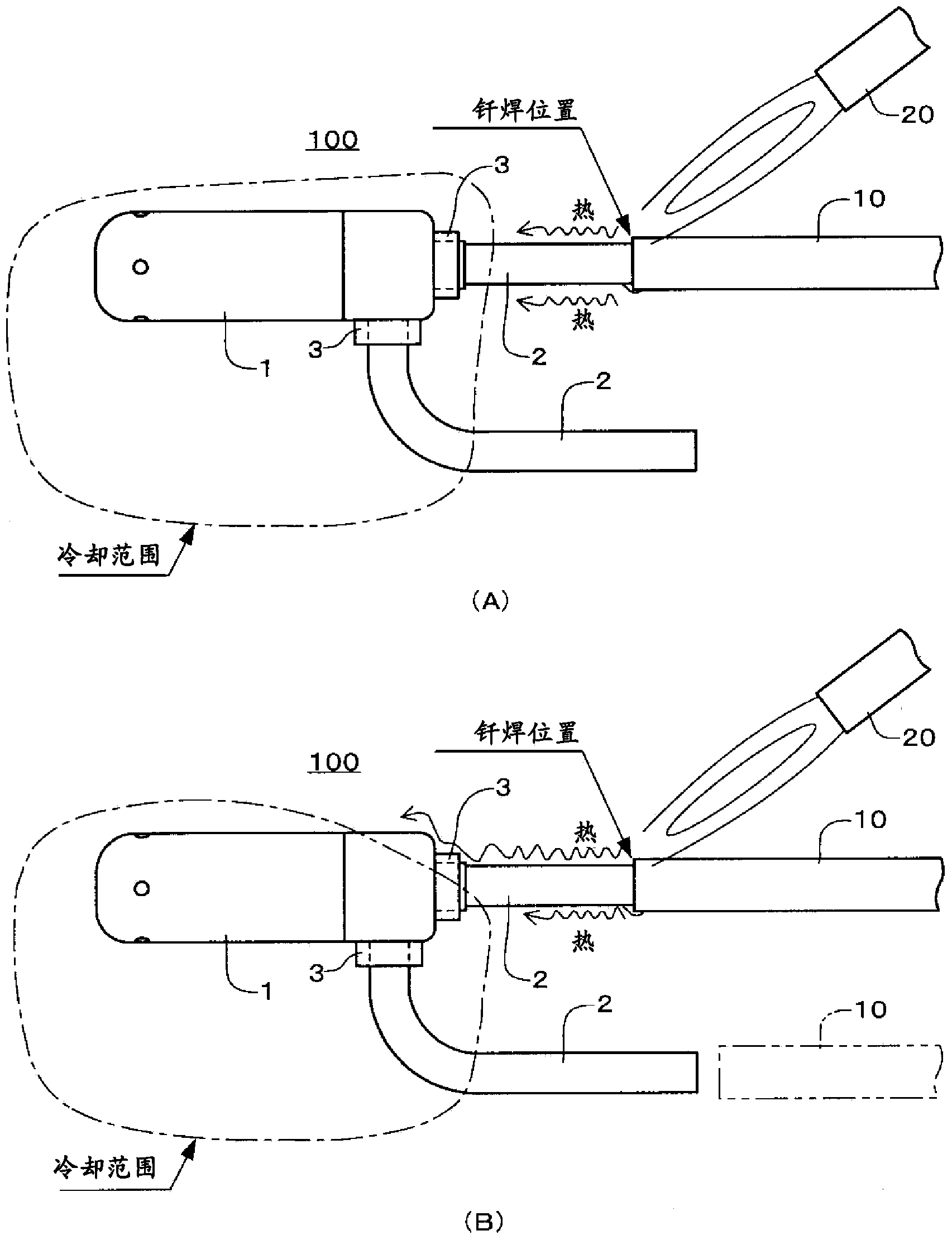
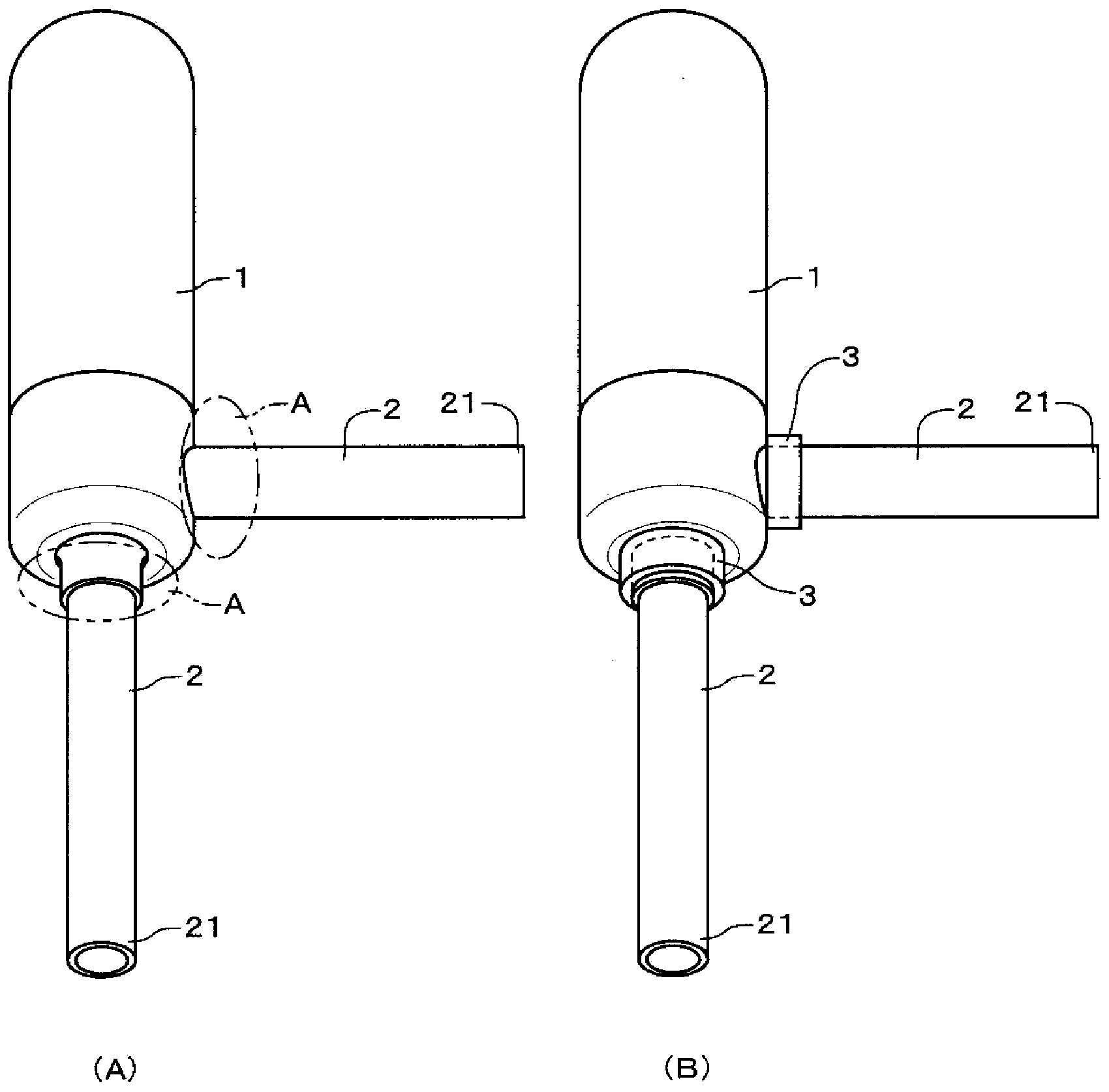
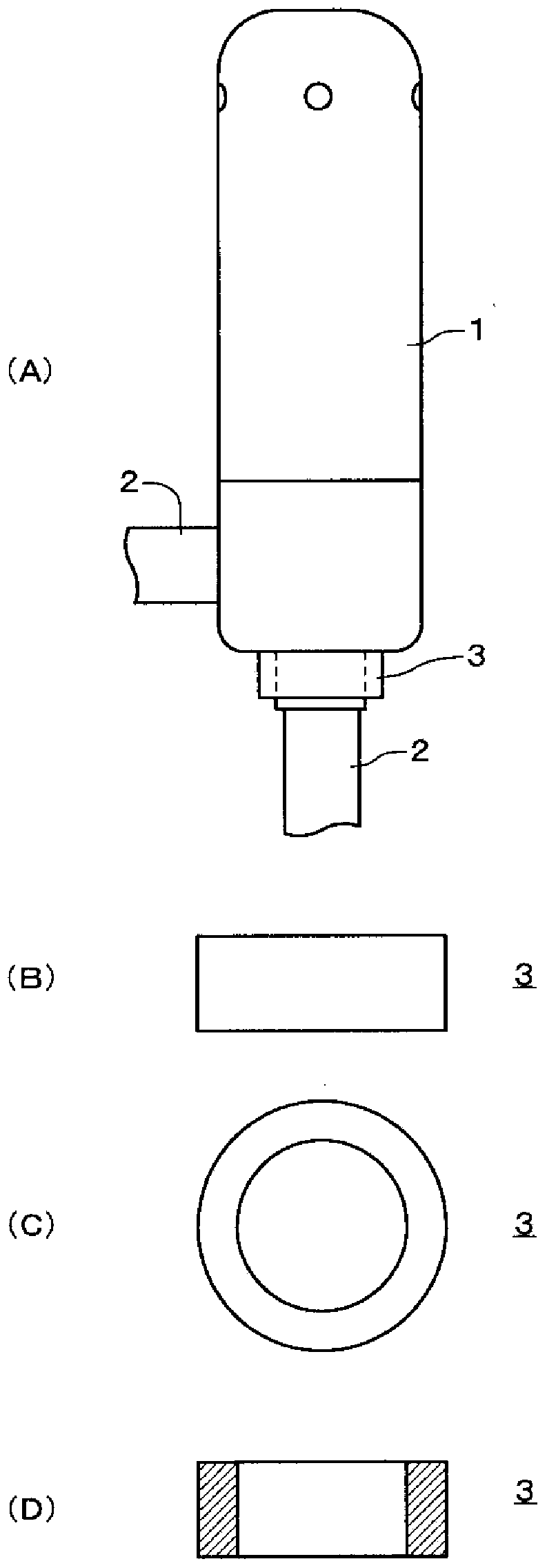
[0026] Hereinafter, embodiments of the present invention will be described with reference to the drawings. The embodiment is an example in which the fluid control device is an electric valve and the electric valve is brazed to the piping of the refrigeration cycle system (fluid circulation system). figure 1 It shows a state where the electric valve of the embodiment of the present invention has been well brazed ( figure 1 (A)), and the state where the brazing operation is not performed well ( figure 1 (B)). figure 2 Is a perspective view of the electric valve of the embodiment, figure 2 (A) is the state before the indicator 3 is installed, figure 2 (B) shows the state after the indicator 3 is installed. image 3 Is a diagram showing the detailed structure of the main part of the indicator 3 of the embodiment, image 3 (A) is a side view of the installation state of indicator 3, image 3 (B) is a side view of indicator 3, image 3 (C) is the bottom view of indicator 3. image 3 ...


PUM


Abstract

The present invention relates to an excess temperature detection method and a set of fluid control equipment in tubing soldering. When soldering is performed for a joint (2) and tubing (10) of an electric valve (100), whether the heat in soldering affects the components in a body part (1) can be easily determined through a simple structure. An indicator (3) is provided at a root part at a body part (1) side of the joint (2) through a mode of covering the full periphery of the joint (2). The indicator (3) is formed by the synthetic resin as thermoplastic component. While the body part (1) and the indicator (3) are cooled, soldering is performed for the joint (2) and the tubing (10). After soldering, deformation, metamorphosis, etc. of the indicator (3) are confirmed through vision. The indicator (3) can be a cylindrical component, a component which is provided with a plurality of cross grooves on the cylindrical shape, a component which is provided with a plurality of longitudinal grooves on the cylindrical shape, or an annular component. Furthermore the excess indicator can be a clamp-shaped or grid-shaped component. The excessive temperature detection method and the fluid control equipment in tubing soldering can be used for four-way switch valve and electromagnetic valve.

Description

[0001] The present invention is a divisional application of an invention application with an application number of 201110047384.9, an invention title of "Excess temperature detection method and fluid control equipment for pipe brazing", and an application date of February 23, 2011. Technical field [0002] The present invention relates to a method for detecting excess temperature during piping brazing and fluid control equipment for detecting excess temperature when the equipment and the piping of the system are joined by brazing in a fluid control device installed on a circuit of a fluid circulation system such as a valve device . Background technique [0003] Conventionally, as a method of joining fluid control equipment such as a valve device to a pipe of a fluid circulation system, there have been many methods of brazing joints of the equipment and the pipe. The brazing operation is performed at the tip of the joint which is tens of mm away from the main body of the fluid cont...

Claims


Application Information

Patent Timeline
Patent Type & Authority Applications(China)
IPC IPC(8): B23K1/20B23K3/08
CPCB23K1/20B23K3/08
Inventor 平川尚中野诚一中川大树
Owner SAGINOMIYA SEISAKUSHO INC
Why Eureka
Try Eureka