Excess temperature detection method and fluid control equipment in tubing soldering

A technology of control equipment and detection methods, applied in welding equipment, metal processing equipment, manufacturing tools, etc., can solve the problems of labor and time required for temperature detection, heat transfer to the inside of the main body, and inability to detect heat transfer, etc.

CN102189306AInactive Publication Date: 2011-09-21SAGINOMIYA SEISAKUSHO INC
4 Cites 0 Cited by

Patent Information

Authority / Receiving Office
CN · China
Patent Type
Applications(China)
Current Assignee / Owner
Publication Date
2011-09-21
Estimated Expiration
Not applicable · inactive patent

Smart Images

  • Figure 1
    Figure 1
  • Figure 2
    Figure 2
  • Figure 3
    Figure 3
Patent Text Reader

Abstract

The present invention relates to an excess temperature detection method and a set of fluid control equipment in tubing soldering. When soldering is performed for a joint (2) and tubing (10) of an electric valve (100), whether the heat in soldering affects the components in a body part (1) can be easily determined through a simple structure. An indicator (3) is provided at a root part at a body part (1) side of the joint (2) through a mode of covering the full periphery of the joint (2). The indicator (3) is formed by the synthetic resin as thermoplastic component. While the body part (1) and the indicator (3) are cooled, soldering is performed for the joint (2) and the tubing (10). After soldering, deformation, metamorphosis, etc. of the indicator (3) are confirmed through vision. The indicator (3) can be a cylindrical component, a component which is provided with a plurality of cross grooves on the cylindrical shape, a component which is provided with a plurality of longitudinal grooves on the cylindrical shape, or an annular component. Furthermore the excess indicator can be a clamp-shaped or grid-shaped component. The excessive temperature detection method and the fluid control equipment in tubing soldering can be used for four-way switch valve and electromagnetic valve.
Need to check novelty before this filing date? Find Prior Art

Description

technical field

[0001] The present invention relates to a method for detecting excess temperature during brazing of pipes and a fluid control device for detecting excess temperature when brazing is used to detect excess temperature in a fluid control device installed in a circuit of a fluid circulation system such as a valve device and a pipe of the system . Background technique

[0002] Conventionally, as a method of joining fluid control equipment such as a valve device to piping in a fluid circulation system, there are many methods of brazing joints of equipment and piping. The brazing work is performed by applying heat over 3000°C to the front end of the joint tens of mm away from the main body of the fluid control equipment when acetylene gas welding is performed, but at this time there is a possibility that the function of the fluid control equipment will be significantly damaged. . For example, thermal deformation of components inside the main body of the fluid cont...

Examples

Embodiment Construction

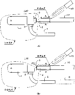
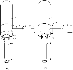
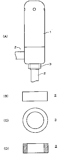
[0025] Embodiments of the present invention will be described below with reference to the drawings. The embodiment is an example in which the fluid control device is an electric valve, and the electric valve is brazed to piping of a refrigeration cycle system (fluid cycle system). figure 1 It shows the state that the brazing work has been performed satisfactorily on the electric valve according to the embodiment of the present invention ( figure 1 (A)), and the state that the brazing operation has not been performed well ( figure 1 (B)). figure 2 is a perspective view of the electric valve of the embodiment, figure 2 (A) shows the state before the indicator 3 is installed, figure 2 (B) shows the state after the indicator 3 is attached. image 3 It is a figure which shows the detailed structure of the main part of the indicator 3 of embodiment, image 3 (A) is a side view of the installed state of the indicator 3, image 3 (B) is a side view of indicator 3, image 3 (...