Excess temperature detection method and fluid control equipment in tubing soldering

一种控制设备、检测方法的技术,应用在焊接设备、金属加工设备、制造工具等方向,能够解决不能检测传热、热传到主体内部、检测温度需要劳力和时间等问题

Inactive Publication Date: 2015-01-14
SAGINOMIYA SEISAKUSHO INC
View PDF4 Cites 0 Cited by
  • Summary
  • Abstract
  • Description
  • Claims
  • Application Information

AI Technical Summary

Problems solved by technology

In this brazing operation, the main body of the valve unit is usually cooled, however, there may be cases where heat is transferred to the inside of the main body through the joint due to some malfunction.
[0009] However, in the case where heat transfer occurs in a part of the joint, as far as the method of using the temperature-indicating member or the temperature-indicating paint of the above-mentioned Patent Documents 1 to 3 is concerned, if there is a temperature-indicating member or the like in a part of the joint where heat transfer does not occur, it cannot be detected. its heat transfer
Furthermore, in the temperature-indicating members and temperature-indicating paints of Patent Documents 1 to 3, although the temperature itself can be judged, there is a problem that labor and time are required to set the detected temperature and the like.

Method used


Image

  • Excess temperature detection method and fluid control equipment in tubing soldering
  • Excess temperature detection method and fluid control equipment in tubing soldering
  • Excess temperature detection method and fluid control equipment in tubing soldering

Examples


Embodiment Construction

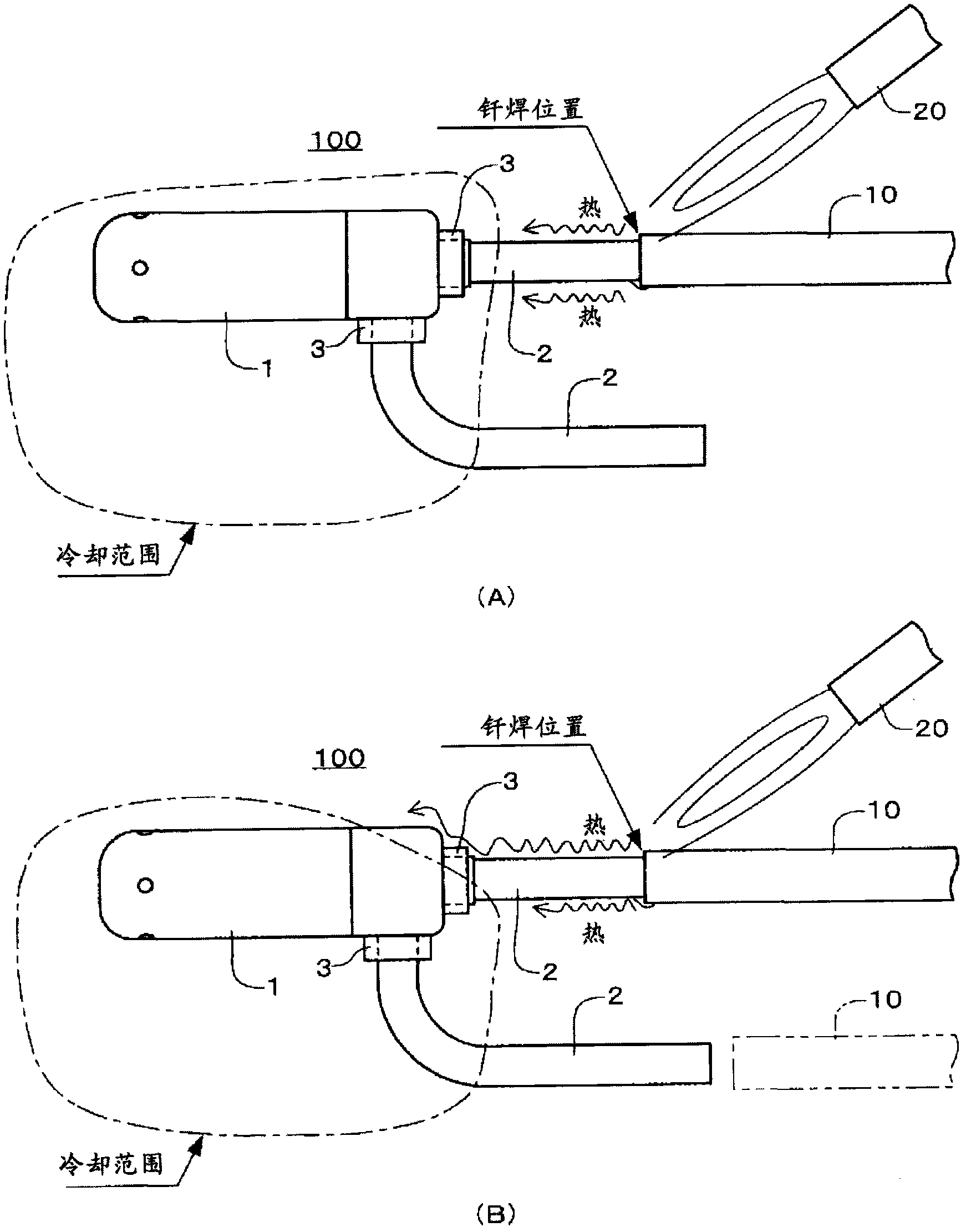
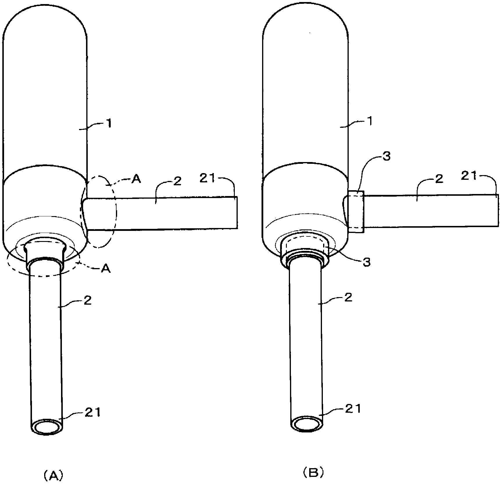
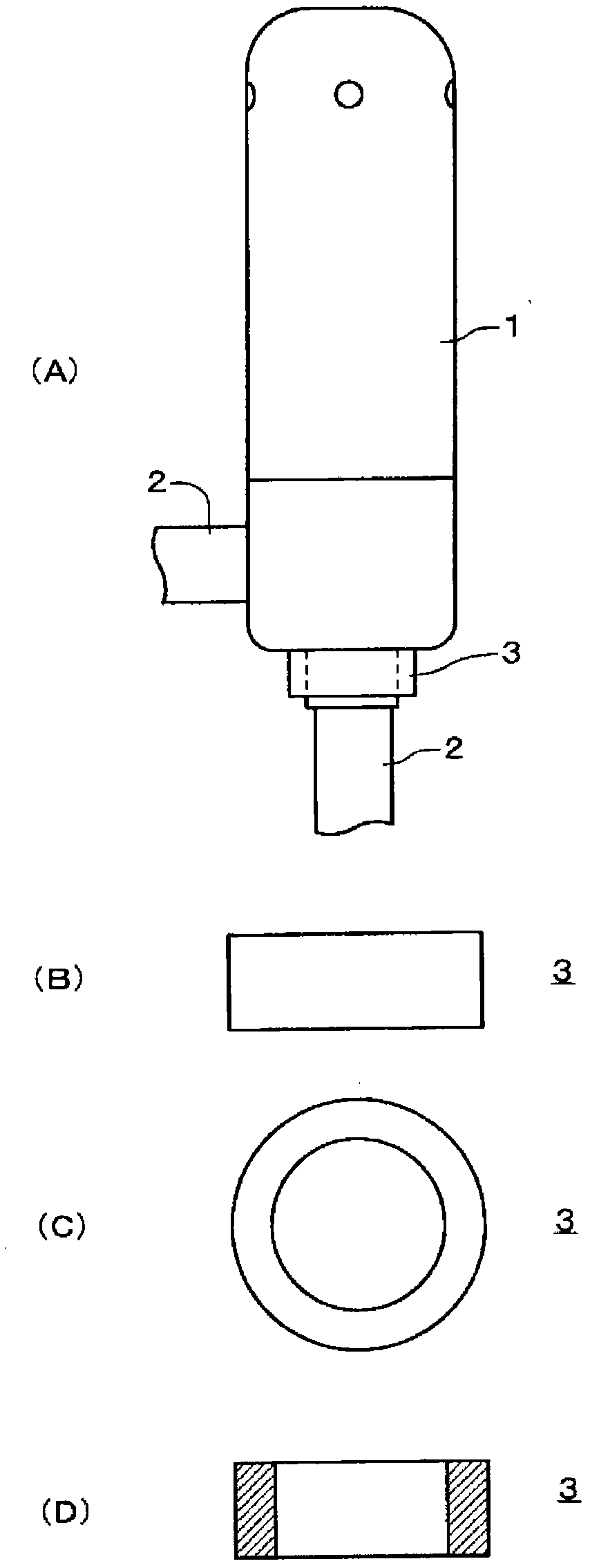
[0025] Embodiments of the present invention will be described below with reference to the drawings. The embodiment is an example in which the fluid control device is an electric valve, and the electric valve is brazed to piping of a refrigeration cycle system (fluid cycle system). figure 1 It shows the state that the brazing work has been performed satisfactorily on the electric valve according to the embodiment of the present invention ( figure 1 (A)), and the state that the brazing operation has not been performed well ( figure 1 (B)). figure 2 is a perspective view of the electric valve of the embodiment, figure 2 (A) shows the state before the indicator 3 is installed, figure 2 (B) shows the state after the indicator 3 is attached. image 3 It is a figure which shows the detailed structure of the main part of the indicator 3 of embodiment, image 3 (A) is a side view of the installed state of the indicator 3, image 3 (B) is a side view of indicator 3, image 3 (...


PUM


Abstract

The present invention relates to an excess temperature detection method and a set of fluid control equipment in tubing soldering. When soldering is performed for a joint (2) and tubing (10) of an electric valve (100), whether the heat in soldering affects the components in a body part (1) can be easily determined through a simple structure. An indicator (3) is provided at a root part at a body part (1) side of the joint (2) through a mode of covering the full periphery of the joint (2). The indicator (3) is formed by the synthetic resin as thermoplastic component. While the body part (1) and the indicator (3) are cooled, soldering is performed for the joint (2) and the tubing (10). After soldering, deformation, metamorphosis, etc. of the indicator (3) are confirmed through vision. The indicator (3) can be a cylindrical component, a component which is provided with a plurality of cross grooves on the cylindrical shape, a component which is provided with a plurality of longitudinal grooves on the cylindrical shape, or an annular component. Furthermore the excess indicator can be a clamp-shaped or grid-shaped component. The excessive temperature detection method and the fluid control equipment in tubing soldering can be used for four-way switch valve and electromagnetic valve.

Description

technical field [0001] The present invention relates to a method for detecting excess temperature during brazing of pipes and a fluid control device for detecting excess temperature when brazing is used to detect excess temperature in a fluid control device installed in a circuit of a fluid circulation system such as a valve device and a pipe of the system . Background technique [0002] Conventionally, as a method of joining fluid control equipment such as a valve device to piping in a fluid circulation system, there are many methods of brazing joints of equipment and piping. The brazing work is performed by applying heat over 3000°C to the front end of the joint tens of mm away from the main body of the fluid control equipment when acetylene gas welding is performed, but at this time there is a possibility that the function of the fluid control equipment will be significantly damaged. . For example, thermal deformation of components inside the main body of the fluid cont...

Claims


Application Information

Patent Timeline
Patent Type & Authority Patents(China)
IPC IPC(8): B23K1/20B23K3/08
CPCB23K1/20B23K3/08
Inventor 平川尚中野诚一中川大树
Owner SAGINOMIYA SEISAKUSHO INC
Why Eureka
Try Eureka