Steel pipe cutting positioning device

A technology for positioning devices and steel pipes, which is applied to tubular objects, gas flame welding equipment, applications, etc. It can solve the problems of affecting efficiency, high price, and bulkiness, and achieve the effects of easy portability, regular cuts, and light weight

Active Publication Date: 2014-10-01
PETROCHINA CO LTD
View PDF7 Cites 0 Cited by
  • Summary
  • Abstract
  • Description
  • Claims
  • Application Information

AI Technical Summary

Problems solved by technology

[0002] When cutting steel pipes, due to the influence of manual line drawing errors and the technical level of gas welders, it is often necessary to cut and repair repeatedly, which not only affects the efficiency, but also makes it difficult to guarantee the quality. The use of automatic and semi-automatic cutting equipment can improve cutting quality and efficiency. At present Commonly used automatic and semi-automatic cutting equipment (magnetic automatic cutting machine, chain automatic pipe cutting machine, positioning block type pipe cutting machine, track chain compound automatic pipe cutting machine, etc.) need to be positioned on the outer wall of the pipeline, which is relatively heavy and expensive High, not suitable for small construction teams with strong mobility

Method used


Image

  • Steel pipe cutting positioning device
  • Steel pipe cutting positioning device

Examples


Embodiment Construction

[0023] The specific implementation manners of the present invention will be described in further detail below in conjunction with the accompanying drawings.

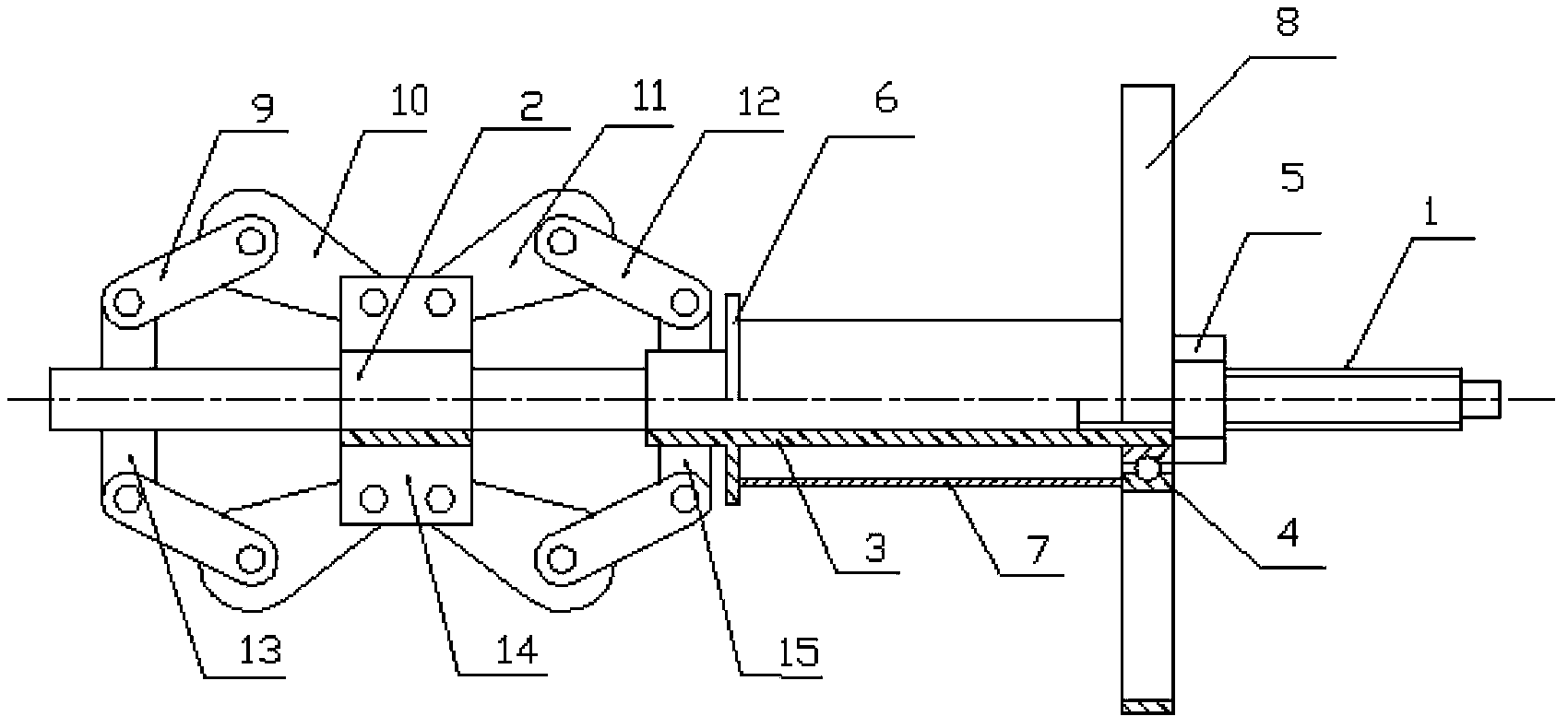
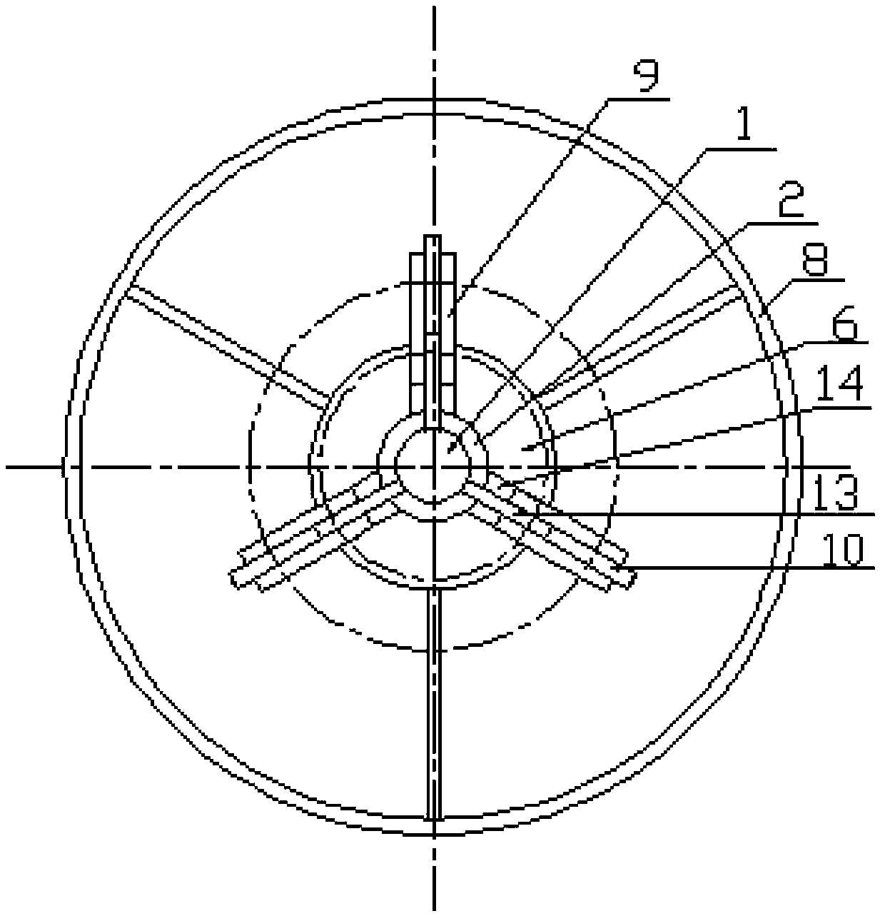
[0024] Such as figure 1 As shown, the steel pipe cutting positioning device of the present invention consists of a tensioning pull rod 1, a traveling sleeve 2, a positioning sleeve 3, a bearing 4, a lock nut 5, a baffle plate 6, a protective tube 7, a cutting torch installation accessory 8, and a first positioning Support sheet 9, the second positioning support sheet 10, the third positioning support sheet 11, the fourth positioning support sheet 12, the first fixed sheet 13, the second fixed sheet 14, and the third fixed sheet 15. One end of the tensioning rod 1 is a screw thread, the end is a square head, and the other end is welded with three first fixed pieces 13 distributed at 120°. There is a screw hole on the first fixed piece 13; On the tie rod 1, adjacent to the first fixed piece 13 on the tensioning tie rod 1,...


PUM


Abstract

The invention relates to a steel pipe cutting positioning device. The steel pipe cutting positioning device comprises a tensioning pull rod, a movable sleeve, a positioning sleeve, a bearing, a retaining plate, a protection pipe, a cutting torch mounting accessory, multiple groups of positioning support sheets, multiple groups of fixing sheets and the like. The corresponding fixing sheets are welded to one end of the tensioning pull rod, the movable sleeve sleeves the tensioning pull rod, the corresponding fixing sheets are welded onto the movable sleeve, the positioning sleeve sleeves the tensioning pull rod close to the movable sleeve, the corresponding fixing sheets are welded to one end, close to the movable sleeve, of the positioning sleeve, the retaining plate is welded on the positioning sleeve and close to the fixing sheets, the protection pipe sleeves the middle of the positioning sleeve, the bearing is mounted at the other end of the positioning sleeve and sleeved with the cutting torch mounting accessory, the positioning support sheets in all the groups are identical in number, the fixing sheets are movably connected with the corresponding positioning support sheets, and first positioning support sheets, fourth positioning support sheets and second fixing sheets are respectively clamped on two sides of first fixing sheets, second positioning support sheets, third positioning support sheets and third fixing sheets connected with two ends thereof. The steel pipe cutting positioning device is mainly used for effective positioning when steel pipes are cut.

Description

technical field [0001] The invention relates to a positioning device used in steel pipe cutting. Background technique [0002] When cutting steel pipes, due to the influence of manual line drawing errors and the technical level of gas welders, it is often necessary to cut and repair repeatedly, which not only affects the efficiency, but also makes it difficult to guarantee the quality. The use of automatic and semi-automatic cutting equipment can improve cutting quality and efficiency. At present Commonly used automatic and semi-automatic cutting equipment (magnetic automatic cutting machine, chain automatic pipe cutting machine, positioning block type pipe cutting machine, track chain compound automatic pipe cutting machine, etc.) need to be positioned on the outer wall of the pipeline, which is relatively heavy and expensive High, not suitable for small construction teams with strong mobility. Contents of the invention [0003] In view of the above-mentioned defects in ...

Claims


Application Information

Patent Timeline
Patent Type & Authority Applications(China)
IPC IPC(8): B23K7/10
CPCB23K7/007B23K7/10B23K2101/06
Inventor 孙爱国赵学勇孙书坤李勇宗志强李士澜韩继勇张洪坤田寿军田伟刘建林徐希成刘诚王军王森香
Owner PETROCHINA CO LTD
Why Eureka
Try Eureka