Spinning machine

A textile machine and textile board technology, which is applied in textiles, textiles, papermaking, and auxiliary equipment for weaving. It can solve the problems of low dust absorption efficiency, improve air quality, increase production costs, and reduce pollution.

Inactive Publication Date: 2018-11-06
枝江市凯达纺织有限责任公司
View PDF0 Cites 0 Cited by
  • Summary
  • Abstract
  • Description
  • Claims
  • Application Information

AI Technical Summary

Problems solved by technology

[0004] The purpose of the present invention is to provide a textile machine to solve the technical problem of low dust absorption efficiency in textile workshops in the prior art.

Method used


Image

  • Spinning machine
  • Spinning machine

Examples


Embodiment Construction

[0012] The technical solution of the present invention will be further described below in conjunction with the drawings and embodiments.

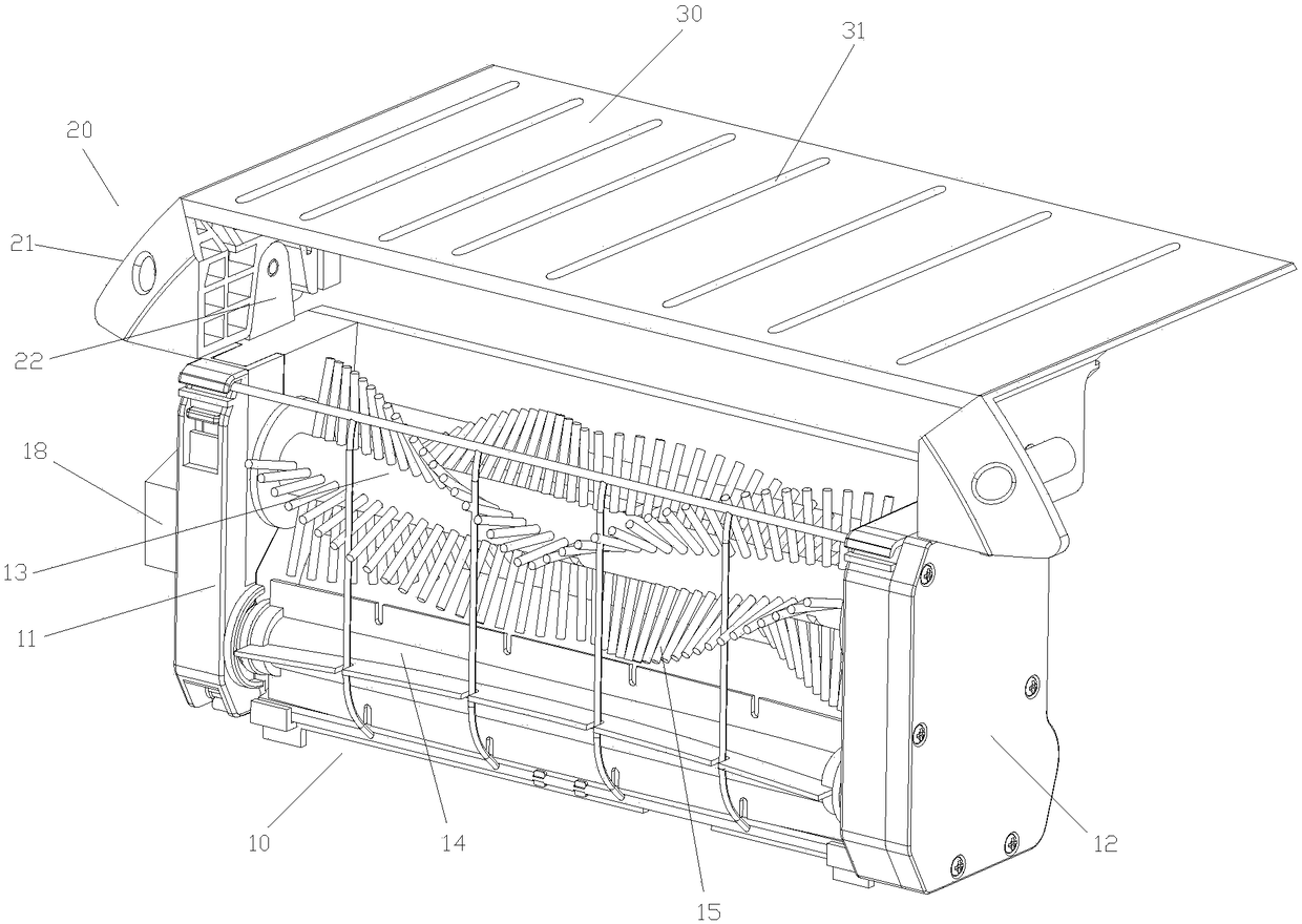
[0013] Such as figure 1 with figure 2 As shown, as a preferred embodiment, the present invention proposes a textile machine, which includes a dust suction device 10 and a textile board 30. The dust suction device 10 includes a left fixing plate 11 and a right fixing plate 12, the left fixing An absorption main pipe 13 and a collecting pipe 14 are fixedly connected between the plate 11 and the right fixing plate 12. The right fixing plate 12 has a cavity, and the absorption main pipe 13 and the collecting pipe 14 are fixedly connected to the right fixing plate 12 The cavities are in communication, the absorption main pipe 13 is provided with multiple rows of absorption capillaries 15 along the axial direction, and the absorption capillaries 15 are provided with a number of through holes (for aesthetics, not shown in the figure), the collection...


PUM

PropertyMeasurementUnit
diameteraaaaaaaaaa

Abstract

The invention relates to a spinning machine. The spinning machine comprises a dust sucking device and a spinning board, wherein the dust sucking device comprises a left fixing plate and a right fixingplate; a sucking main tube and a collecting tube are fixedly connected between the left fixing plate and the right fixing plate; a cavity is formed in the right fixing plate; the sucking main tube and the collecting tube are fixedly connected to the right fixing plate and then communicated with the cavity; multiple rows of sucking capillary tubes are axially arranged on the sucking main tube; a plurality of through holes are formed in the sucking capillary tubes; multiple layers of filter screens are radially arranged inside the collecting tube; a plurality of filter holes are formed in the filter screens; a suction fan is fixedly connected to the left fixing plate; a suction port of the suction fan is connected with the sucking main tube; connecting assemblies are symmetrically arrangedon the left fixing plate and the right fixing plate; each connecting assembly comprises an inclinedly arranged connecting plate and a supporting plate fixedly connected to the lower side of the connecting plate; the spinning board is horizontally fixedly connected between the two inclinedly arranged connecting plates; a plurality of ventilating slots are formed in the spinning board. The spinningmachine provided by the invention has the effect of efficiently sucking dust.

Description

Technical field [0001] The invention relates to the technical field of textile equipment, in particular to a textile machine. Background technique [0002] When the textile machine is working, a large amount of dust is generated. The existing textile machine has no dust absorption and treatment device, which will cause greater physical harm to workers. [0003] In order to reduce personal injury to workers, some textile factories use enhanced ventilation to improve environmental conditions, but the dust absorption efficiency is low. Summary of the invention [0004] The purpose of the present invention is to provide a textile machine in view of the shortcomings in the above-mentioned background technology to solve the technical problem of low dust absorption efficiency in textile workshops in the prior art. [0005] In order to achieve the above objectives, the present invention adopts the following technical solutions: [0006] A textile machine includes a dust suction device and a t...

Claims


Application Information

Patent Timeline
Patent Type & Authority Applications(China)
IPC IPC(8): D01H11/00D03J1/00
CPCD01H11/005D03J1/002
Inventor 张宇
Owner 枝江市凯达纺织有限责任公司
Why Eureka
Try Eureka