Feeding device of impeller insertion sheet

A feeding device and inserting technology, which is applied in metal processing, metal processing equipment, manufacturing tools, etc., can solve the problems of inaccurate material picking, jammed inserts, breakage, etc., so as to improve the degree of automatic operation, ensure reliability, The effect of improving accuracy

Active Publication Date: 2014-10-01
嘉兴市朗盛机械有限公司
View PDF7 Cites 11 Cited by
  • Summary
  • Abstract
  • Description
  • Claims
  • Application Information

AI Technical Summary

Problems solved by technology

However, the blades of the insert impeller are not in a plane structure, but have a certain radian. After multiple arc-shaped blades are superimposed, the arc-shaped surfaces between the blades will interfere and affect the discharge. It is difficult to take the material directly from the outlet. The material port directly pushes the blades from one side, which is easy to cause the problem that multiple blades fall out of the material outlet at one time, and the material cannot be picked up accurately; moreover, there are protruding inserts at both ends of the main body of the blades, and the blades are put into the After the material box, it is easy to get stuck or break the insert in the process of retrieving the material. Therefore, the traditional feeding device cannot guarantee that the blades of the insert impeller can be discharged and retrieved normally, and further improvements and improvements are needed. new structural design

Method used


Image

  • Feeding device of impeller insertion sheet
  • Feeding device of impeller insertion sheet
  • Feeding device of impeller insertion sheet

Examples


Embodiment Construction

[0019] The present invention will be further described in detail below in conjunction with the accompanying drawings and embodiments.

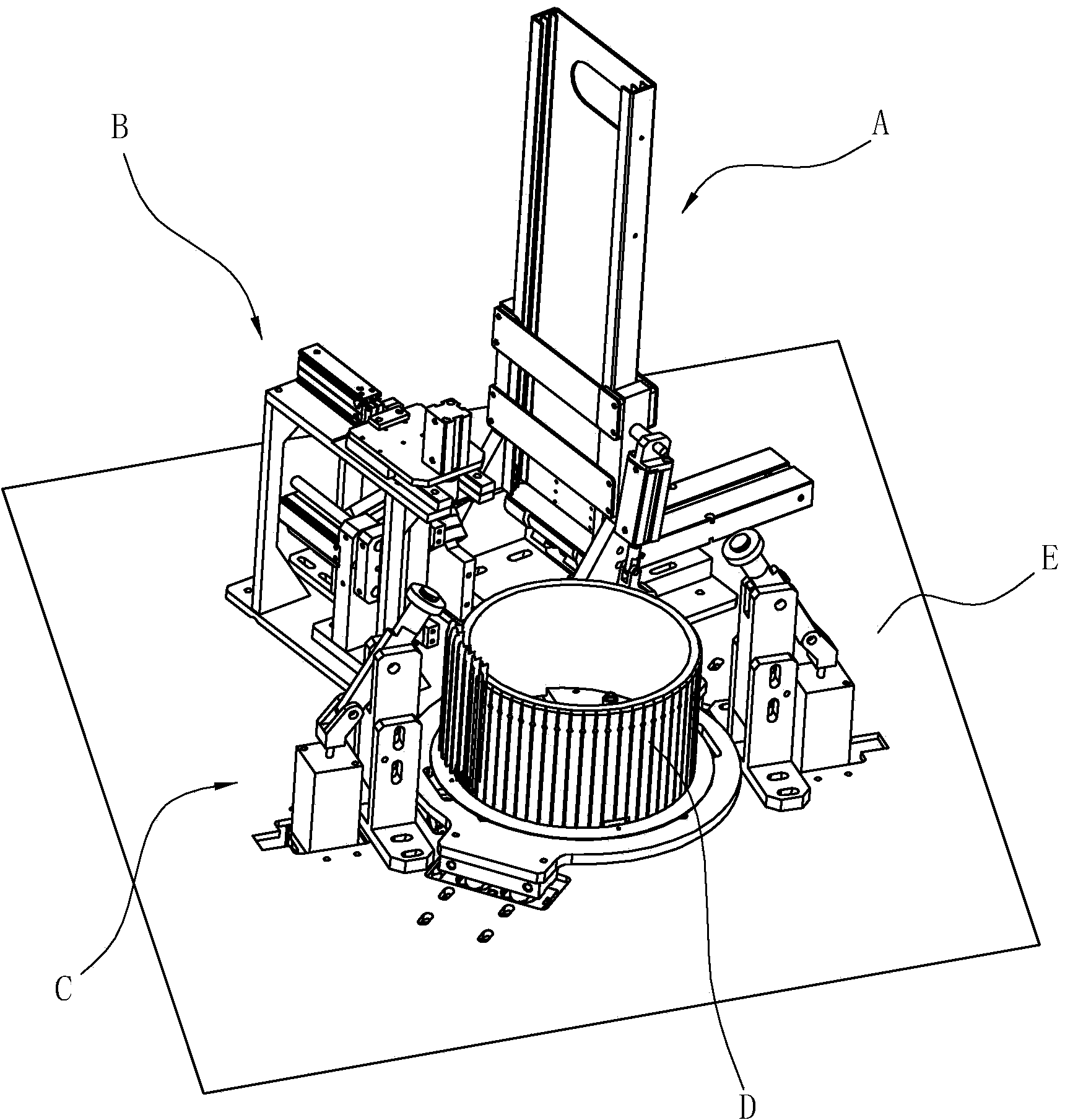
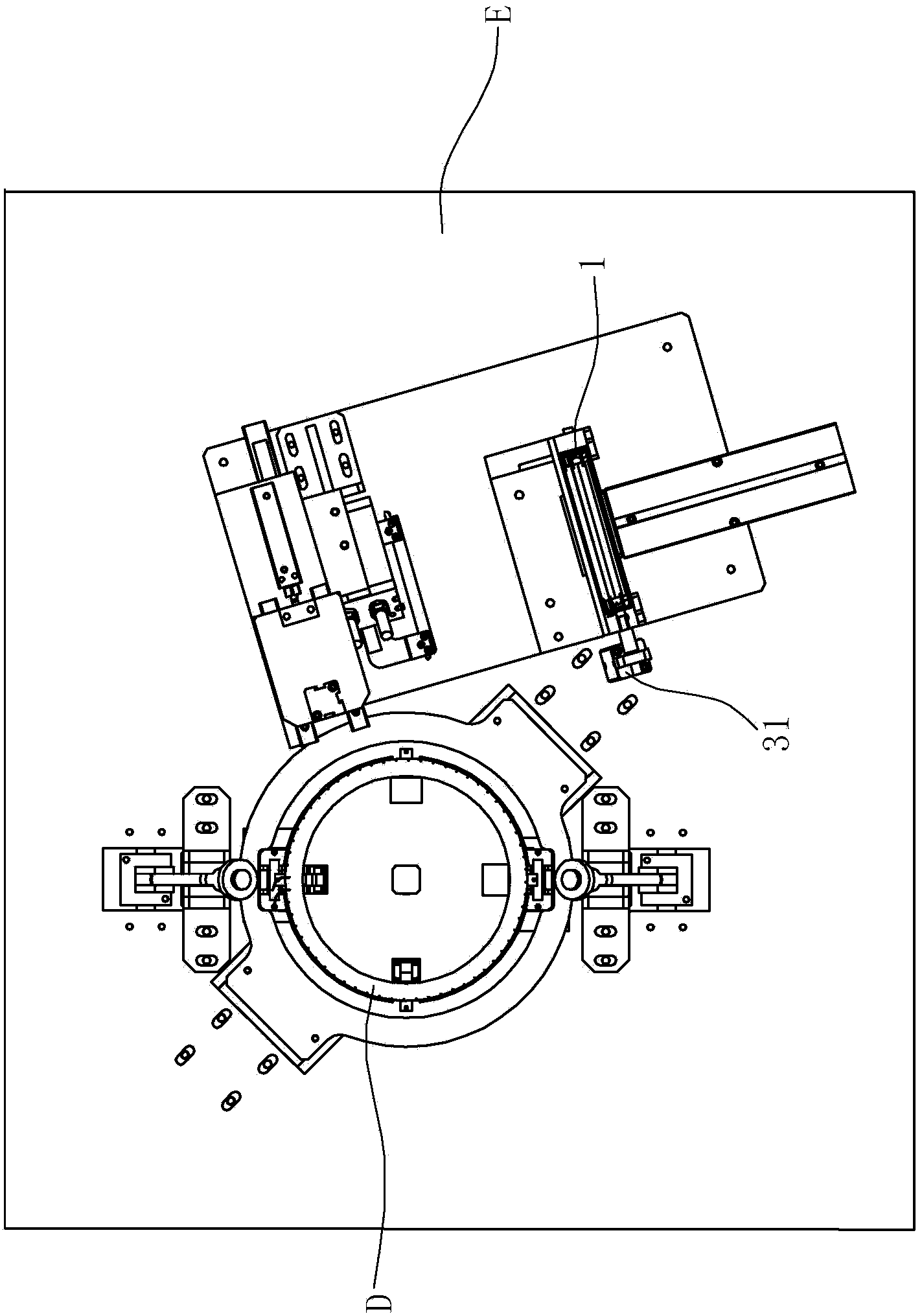
[0020] Such as Figure 1 to Figure 7 As shown, this embodiment discloses a feeding device for inserting blades of an impeller. The feeding device is arranged on the automatic forming equipment of the bladed impeller. The automatic forming equipment includes an organic base E, and the base E is provided with a feeding device A, Reclaiming device B, rolling riveting device C and mold D for impeller insertion, see figure 1 and figure 2 , wherein the mold D includes a hollow cylinder, and the cylinder of the mold D has slots arranged at intervals along the circumference for inserting blades.

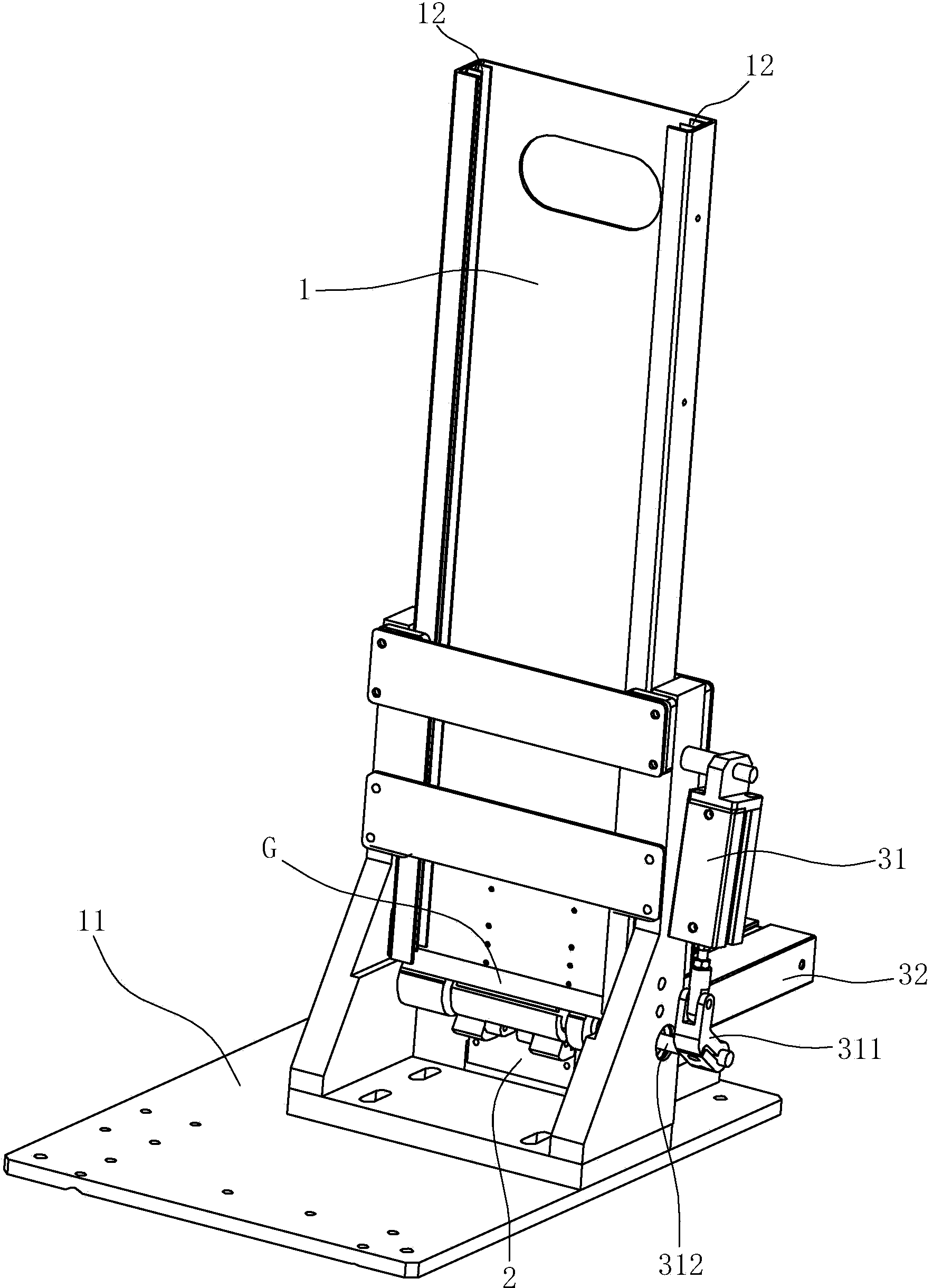
[0021] The feeding device A includes a material box 1 capable of accommodating the blade G, a first drive mechanism and a base 11 that can drive the blade G out of the material box 1, the top of the material box 1 is the material feeding port, and the bot...


PUM


Abstract

The invention discloses a feeding device of an impeller insertion sheet, which comprises a feeding hole and a discharge hole. The feeding device of the impeller insertion sheet is characterized by further comprising a material box and a first drive mechanism capable of driving an impeller to pull away from the material box, wherein the first drive mechanism comprises a first cylinder, a connecting rod, a rotating shaft, a second cylinder and a push block; the two ends of the connecting rod are respectively connected with a piston rod of the first cylinder and one end of the rotating shaft; the piston of the first cylinder is movably hinged to one end of the connecting rod; one end of the rotating shaft is fixedly connected with the other end of the connecting rod; the rotating shaft is arranged on the lower part of the discharge hole of the material box; the rotating shaft includes a circular arc surface adaptive to the profile of the impeller; the push block is located below the rotating shaft and includes a arc surface guide platform adaptive to the profile of the impeller; the piston rod of the second cylinder is connected with the push block. The feeding device of the impeller insertion sheet has the advantages of guaranteeing that one impeller can be taken out per each time as a rotary impeller taking mode is adopted, the impeller material taking precision is improved, automatic conveying of the impeller is realized, the automatic operation degree is improved, and the stability and reliability of the impeller in the material feeding process are guaranteed.

Description

technical field [0001] The invention relates to a feeding device, in particular to a feeding device for impeller blades. Background technique [0002] For example, the Chinese utility model "A fan impeller with simple blade installation" with the patent number of ZL201220105816.7 discloses a blade-type impeller commonly used in range hoods or fans. A plurality of blades, and the upper gland set on the top of the annular distribution blade and the lower gland set on the bottom of the annular distribution blade; wherein, the blades of this insert type impeller are formed with protruding inserts at the upper and lower ends , the insertion piece passes through the slot hole of the upper fixed disk and the lower fixed disk, and the inserted piece is pressed against the end surfaces of the upper fixed disk and the lower fixed disk after being bent. [0003] Usually, a common feeding device is equipped with a material box, and a discharge opening is opened at the bottom of the mat...

Claims


Application Information

Patent Timeline
Patent Type & Authority Applications(China)
IPC IPC(8): B23P19/00
CPCB23P19/001
Inventor 贾世强
Owner 嘉兴市朗盛机械有限公司
Why Eureka
Try Eureka