
Floating centring-type installation device for shaft parts

A technology for installing devices and shaft parts, which is applied in the field of installation of shaft parts in machinery manufacturing and assembly, can solve problems such as limited centering and guiding effects, aggravated press wear, and press-fit impact force, etc., to extend the service life of equipment , Avoid impact and wear, and smooth stuck effect

Inactive Publication Date: 2014-10-01
DALIAN HYDRAULIC COMPONENT
View PDF0 Cites 10 Cited by
  • Summary
  • Abstract
  • Description
  • Claims
  • Application Information

AI Technical Summary

Problems solved by technology

This kind of shaft and bearing rely on their chamfered (rounded) corners as the centering and guiding method. Due to the limitation of the use requirements of the two, the design of the chamfered (rounded) corners is small, which makes the centering and guiding functions during press-fitting limited. , it is very easy for the offset between the two workpieces to cause poor entry or even jamming during press-fitting, thereby scratching the mating surface, affecting the quality of fit, and high product failure rate; at the same time, the impact force of press-fitting is generated, and long-term use will intensify the pressure Wear and tear of the machine increases the failure rate of the equipment

Method used


Image

  • Floating centring-type installation device for shaft parts
  • Floating centring-type installation device for shaft parts

Examples


Embodiment Construction

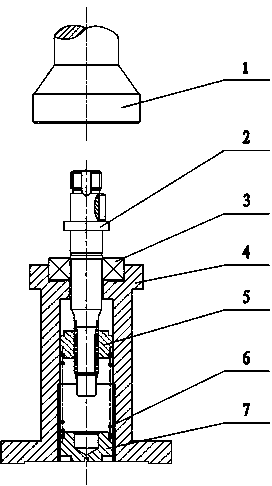
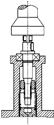
[0010] The structure of the floating centering installation device for shaft parts of the present invention is as follows: figure 1 and figure 2 As shown, the adjusting screw plug 7 is installed on the lower part of the positioning seat 4, the spring 6 is installed on the upper part of the adjusting screw plug 7 inside the positioning seat 4, the floating sliding sleeve 5 is installed on the upper part of the spring 6, and the outer circle of the floating guide sleeve 5 is centered with the inner cavity of the positioning seat 4 Sliding fit installation, the bearing 3 is coaxially installed in the upper positioning hole of the positioning seat 4, the shaft 2 is installed in the inner hole of the bearing 3, the spline part of the lower part of the shaft 2 coincides with the inner hole of the floating guide sleeve 5, and the shaft 2 and the positioning seat 4 coaxial.

[0011] When in use, first put the floating guide sleeve 5 into the positioning seat 4 and then put it into t...


PUM


Abstract

The invention discloses a floating centring-type installation device for shaft parts. According to the floating centring-type installation device for shaft parts, an adjusting plug screw is installed on the lower portion of a location seat; a spring is installed in the location seat and located on the upper portion of the adjusting plug screw; a floating slide sleeve is installed on the upper portion of the spring; the excircle of the floating slide sleeve is installed by being in centring slide fit with the inner cavity of the location seat; a bearing is coaxially installed in the upper location hole of the location seat; a shaft is installed in the inner hole of the bearing; the spline portion of the lower portion of the shaft is superposed with the inner hole of the floating slide sleeve; the shaft is coaxial with the location seat. According to the floating centring-type installation device for shaft parts disclosed by the invention, when the shaft and the bearing are installed, the centring and guide of the shaft and the bearing are always kept from workpiece placement to press-fitting completion, thus ensuring smooth and difficulty-blocked press-fitting process, no scratches on a matching surface and assembly quality, reducing a product fault rate, avoiding impact and wear on press-fitting equipment, prolonging the service duration of the equipment, decreasing the cost, meeting the assembly needs of shafts with various length specifications in a certain range, avoiding machining and use for a plurality of location fixtures, decreasing production cost, and increasing working efficiency.

Description

technical field [0001] The invention relates to the field of installation of shaft parts in mechanical manufacturing and assembly, in particular to the installation technology of steering power pump shafts and bearings. Background technique [0002] At present, in the interference assembly process of the pump shaft and bearing of the power steering hydraulic pump, the positioning seat is generally used to locate, support the workpiece and press the pneumatic press, that is, the positioning seat locates the outer ring of the bearing, supports the bottom of the inner ring of the bearing, and the shaft and the bearing ( Hole) is centered and guided by its chamfered (rounded) corner, and pressed in by a pneumatic press. This kind of shaft and bearing rely on their chamfered (rounded) corners as the centering and guiding method. Due to the limitation of the use requirements of the two, the design of the chamfered (rounded) corners is small, which makes the centering and guiding f...

Claims


Application Information

Patent Timeline
IPC IPC(8): B23P19/02
CPCB23P19/006B23P19/02
Inventor 刘德亮黄文生高梅初晓
Owner DALIAN HYDRAULIC COMPONENT
Learn More