
Liquid ejecting apparatus

A technology of liquid and ejection part, applied in printing devices, printing, typewriters, etc., can solve problems such as recording control failures

Active Publication Date: 2014-10-01
SEIKO EPSON CORP
View PDF7 Cites 8 Cited by
  • Summary
  • Abstract
  • Description
  • Claims
  • Application Information

AI Technical Summary

Problems solved by technology

As a result, there is a problem that ink mist adheres to mechanisms located in this space (for example, a linear scale for control installed on the Y-bar, etc.), causing problems in recording control, etc.

Method used


Image

  • Liquid ejecting apparatus
  • Liquid ejecting apparatus
  • Liquid ejecting apparatus

Examples


Embodiment Construction

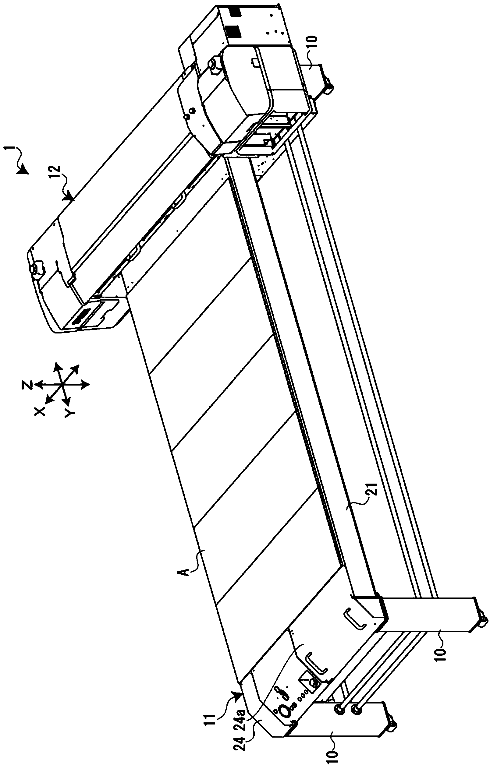
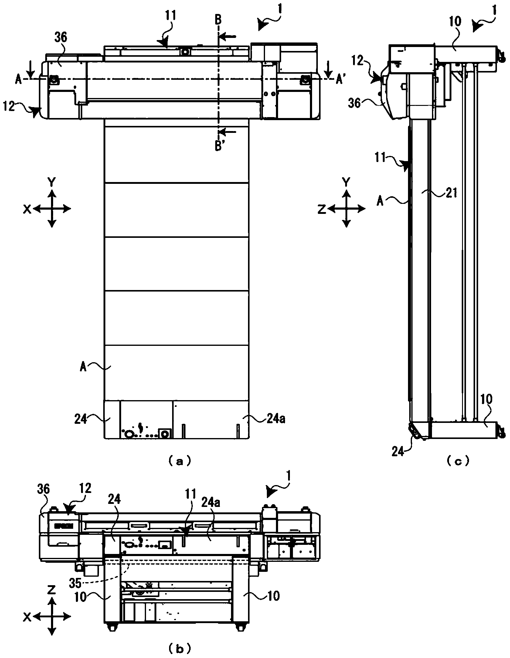
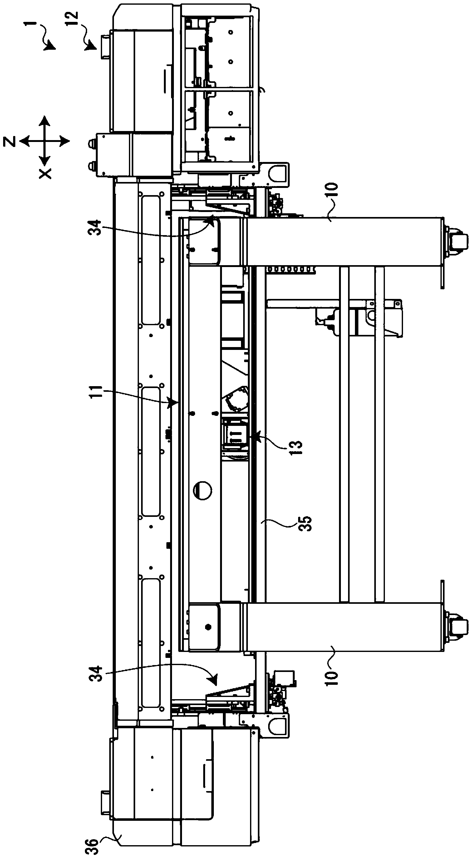
[0031] Hereinafter, a liquid ejection device according to an embodiment of the present invention will be described with reference to the drawings. This liquid ejection device is a liquid ejection device that records a desired image on a recording medium (medium) by ejecting ultraviolet curable ink (active energy ray curable ink) by an inkjet method. In addition, the present liquid ejection device is a so-called flatbed type liquid ejection device that performs recording by moving the liquid ejection head with respect to the recording medium supported on the support stage. As the recording medium, for example, recording media having different thicknesses such as thick paper, wood, ceramic tiles, plastic boards, styrene boards, and corrugated paper are assumed. In addition, the X-axis (left-right direction), the Y-axis (front-rear) direction, and the Z-axis (up-down) direction are defined as shown in each figure, and will be described later. Additionally, the figure 1 The nea...


PUM


Abstract

A liquid ejecting apparatus includes a support stage; a liquid ejecting unit that ejects an ink; an ultraviolet irradiation unit that has an intake port, an exhaust port and a filter; a guide axis that supports the liquid ejecting unit and the ultraviolet irradiation unit; an X-axis driving mechanism that moves the liquid ejecting unit and the ultraviolet irradiation unit; a liquid ejecting portion that has the guide axis and the X-axis driving mechanism; and a ventilation fan that causes a gas to flow between the liquid ejecting portion and the support surface. The ultraviolet irradiation unit is supported by the X-axis driving mechanism on a rear side. The exhaust port is arranged on a front side, and the intake port is arranged thereabove.

Description

technical field [0001] The present invention relates to a liquid ejection device which ejects liquid to a medium. Background technique [0002] Conventionally, as such a liquid ejection device, there is known a liquid ejection device (refer to Patent Document 1) that includes: a table on which a medium is placed; a recording head that ejects ink to the medium; a Y bar , which holds the recording head in a movable manner in the scanning direction; and an airflow generating mechanism, which generates an airflow between the recording head and the medium (gap). By generating an airflow between the recording head and the medium, ink mist, etc. scattered on the medium is removed. [0003] However, in the existing recording device, since the ink mist is removed by generating an air flow only around the gap between the recording head and the medium, although the ink mist scattered on the medium can be removed, it cannot be effectively removed. The problem of accurately removing th...

Claims


Application Information

Patent Timeline
Patent Type & Authority Applications(China)
IPC IPC(8): B41J2/01B41J29/38
CPCB41J2/1714B41J3/28B41J29/02B41J29/13B41J29/377B41J29/38B41J11/0022
Inventor 田中伸一
Owner SEIKO EPSON CORP
Learn More