Vehicle brake hydraulic pressure control apparatus

A brake hydraulic and control device technology, which is applied to brake transmission devices, hydraulic brake transmission devices, brakes, etc., can solve problems such as poor brake operation feeling and decreased rigidity of brake operation

Active Publication Date: 2014-10-01
AUTOLIV NISSIN BRAKE SYST JAPAN CO LTD
View PDF7 Cites 2 Cited by
  • Summary
  • Abstract
  • Description
  • Claims
  • Application Information

AI Technical Summary

Problems solved by technology

As a result, the rigidity of the brake operation is reduced, and the brake operation feeling is not good

Method used


Image

  • Vehicle brake hydraulic pressure control apparatus
  • Vehicle brake hydraulic pressure control apparatus
  • Vehicle brake hydraulic pressure control apparatus

Examples


Embodiment Construction

[0016] Hereinafter, embodiments of the present invention will be described with reference to the drawings.

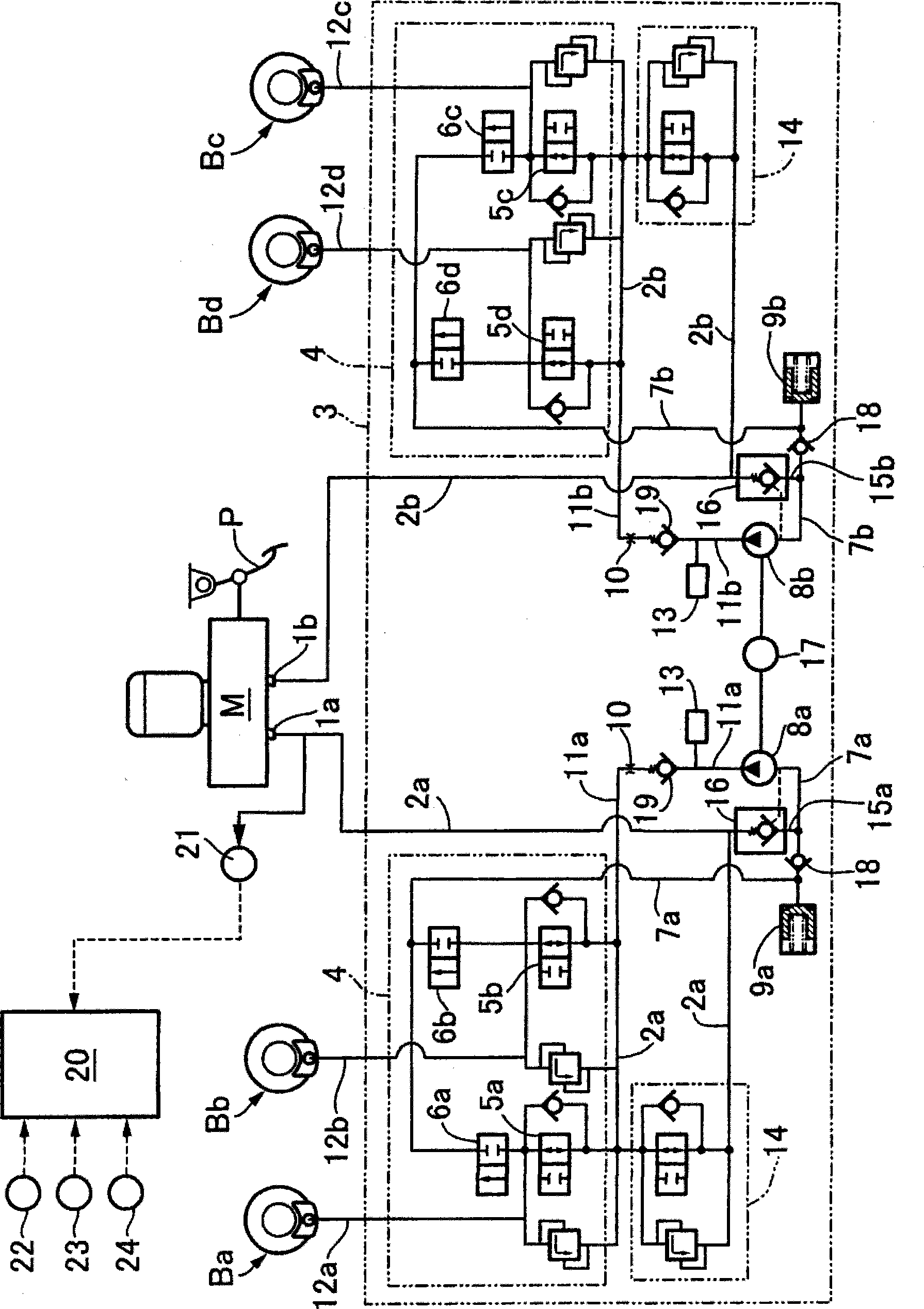
[0017] First, in figure 1 Among them, the master cylinder M is configured as a tandem type, and is provided with a pair of front and rear first and second output ports 1a and 1b for outputting brake hydraulic pressure corresponding to the input from the brake pedal P to the piston. The first and second input paths 2a and 2b are respectively connected to the above-mentioned first and second output ports 1a and 1b. Furthermore, the first to fourth output passages 12a to 12d are connected to the left front wheel brake Ba, the right rear wheel brake Bb, the right front wheel brake Bc, and the left rear wheel brake Bd, respectively. The regulator 3 is installed between the first and second input paths 2a and 2b and the first to fourth output paths 12a to 12d.

[0018] The regulator 3 has a brake control valve arrangement 4 . The brake control valve device 4 has first to f...


PUM


Abstract

A vehicle brake hydraulic control apparatus includes a reservoir, a hydraulic pressure pump, an orifice, a damper and a one-way valve. The reservoir absorbs an excess brake hydraulic pressure of a wheel brake. The hydraulic pressure pump suctions brake fluid absorbed by the reservoir and returns the suctioned brake fluid to a master cylinder through a return line. The orifice is provided in the return line. The damper is connected to the return line between the orifice and the hydraulic pressure pump and damps discharge pressure pulsation of the hydraulic pressure pump. The one-way valve is provided in the return line between the damper and the orifice and prevents a hydraulic flow from an orifice side to a damper side.

Description

technical field [0001] The present invention relates to a brake hydraulic pressure control device for vehicles such as automobiles, and in particular to the improvement of the brake hydraulic pressure control device for vehicles. a hydraulic pump, which sucks the brake fluid absorbed by the reservoir and returns it to the master cylinder via a return passage; an orifice, which is arranged on the return passage; a buffer, which is connected with the orifice and the hydraulic pressure The return passage connection between the pumps attenuates the pulsation of the discharge pressure of the hydraulic pumps. Background technique [0002] Such a vehicle brake hydraulic pressure control device has been disclosed as disclosed in JP2011-226299A. [0003] In the vehicle brake hydraulic pressure control device described in JP2011-220299A, an orifice is provided on a return flow path connecting the discharge side of the hydraulic pump and the master cylinder. However, the damper is co...

Claims


Application Information

Patent Timeline
IPC IPC(8): B60T13/70
CPCB60T11/228B60T8/4872B60T8/4068B60T11/22B60T8/341
Inventor 袰谷正俊增田直己
Owner AUTOLIV NISSIN BRAKE SYST JAPAN CO LTD
Why Eureka
Try Eureka