Constant-speed universal joint driving shaft assembly

A technology of drive shafts and universal joints, applied in the direction of couplings, elastic couplings, mechanical equipment, etc. Affect the service life of the drive shaft assembly and other issues to achieve the effect of enhancing uniformity

Inactive Publication Date: 2014-10-01
CHERY AUTOMOBILE CO LTD
View PDF7 Cites 9 Cited by
  • Summary
  • Abstract
  • Description
  • Claims
  • Application Information

AI Technical Summary

Problems solved by technology

[0005] Due to the non-tight fit between the internal parts of the fixed joint and the moving joint, when the drive shaft assembly of the constant velocity universal joint bears the torque load, the internal parts of the fixed joint and the moving joint will collide during the driving of the vehicle, which will accelerate the The wear of the components in the drive shaft assembly affects the uniformity and stability of the power transmission of the vehicle, affects the service life of the drive shaft assembly, and thus affects the ride comfort, safety, and NVH (Noise, Vibration, Harshness, noise, vibration and roughness), etc.

Method used


Image

  • Constant-speed universal joint driving shaft assembly
  • Constant-speed universal joint driving shaft assembly
  • Constant-speed universal joint driving shaft assembly

Examples


Embodiment

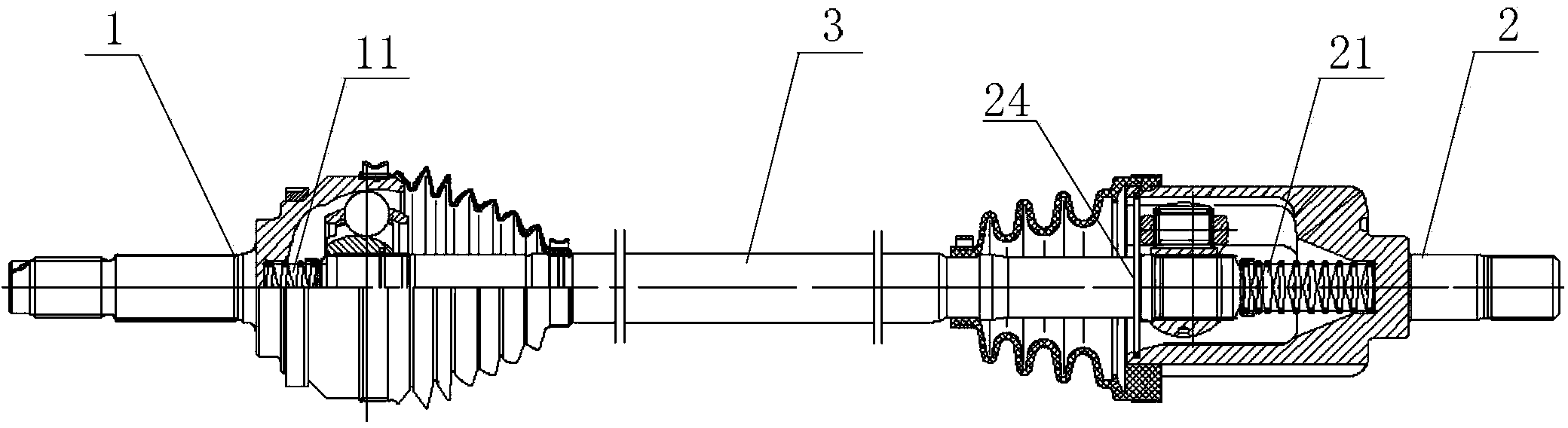
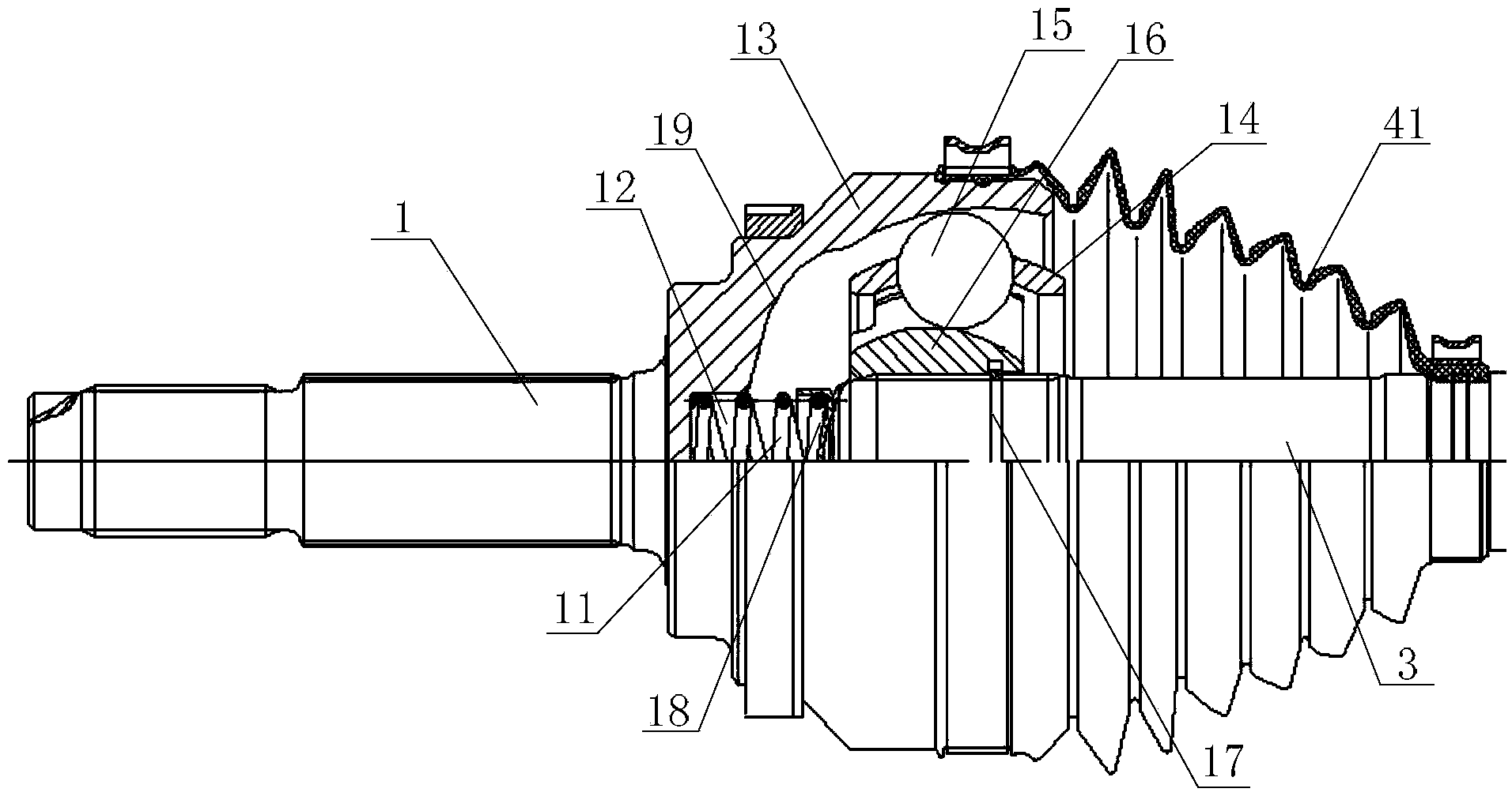
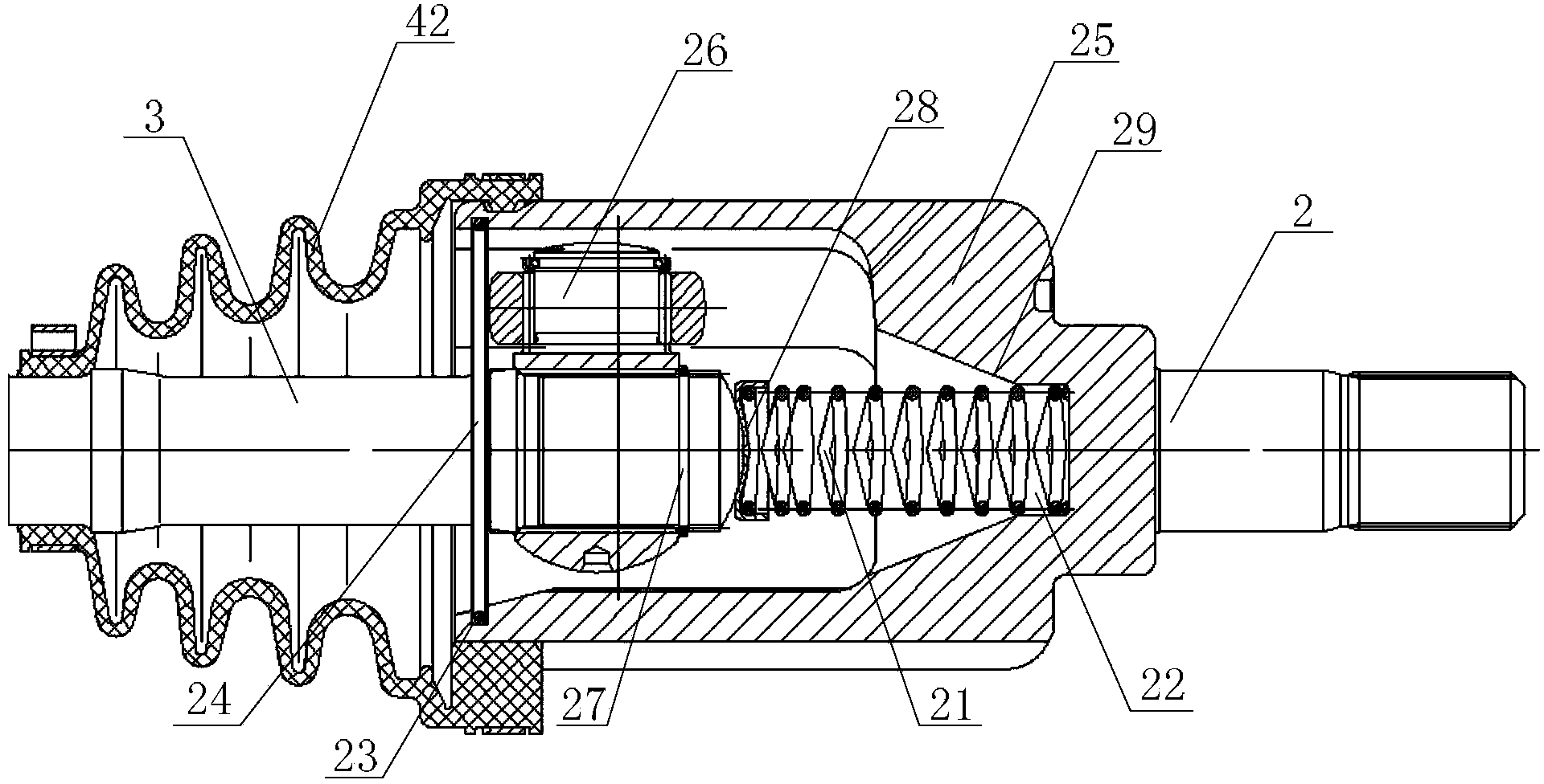
[0024] An embodiment of the present invention provides a constant velocity universal joint drive shaft assembly, see Figure 1-3 , the drive shaft assembly includes a fixed cage universal joint 1, a movable cage universal joint 2, and an intermediate shaft 3 connected to the fixed cage universal joint 1 and the movable cage universal joint 2 at both ends , the fixed ball cage universal joint 1 is provided with a first pressure spring 11, the first pressure spring 11 is arranged along the axial direction of the intermediate shaft 3 and abutted between the fixed ball cage universal joint 1 and one end of the intermediate shaft 3 Between; the mobile cage universal joint 2 is provided with a second pressure spring 21, the second pressure spring 21 is arranged along the axial direction of the intermediate shaft 3 and abutted against one end of the movable cage universal joint 2 and the intermediate shaft 3 between.

[0025] Specifically, in this embodiment, the fixed ball cage uni...


PUM


Abstract

The invention discloses a constant-speed universal joint driving shaft assembly and belongs to the automotive engineering technical field. The constant-speed universal joint driving shaft assembly comprises a fixed ball cage universal joint, a mobile ball cage universal joint and an intermediate shaft; two ends of the intermediate shaft are connected with the fixed ball cage universal joint and the mobile ball cage universal joint respectively; the bottom of an inner chamber of the fixed ball cage universal joint is provided with a cylindrical groove and the bottom of an inner chamber of the mobile ball cage universal joint is provided with a cylindrical groove; a first pressure spring is arranged in the fixed ball cage universal joint; the first pressure spring is arranged along the axial direction of the intermediate shaft and is arranged between the fixed ball cage universal joint and one end of the intermediate shaft in an abutting mode; a second pressure spring is arranged in the mobile ball cage universal joint; the second pressure spring is arranged along the axial direction of the intermediate shaft and is arranged between the mobile ball cage universal joint and the other end of the intermediate shaft in an abutting mode. According to the constant-speed universal joint driving shaft assembly, the first pressure spring abuts against the fixed joint and the intermediate shaft, the second pressure spring abuts against the mobile joint and the intermediate shaft, and accordingly an axial gap formed in the constant-speed universal joint driving shaft assembly is fully offset and the uniformity and the stability of the automotive power transfer are enhanced.

Description

technical field [0001] The invention relates to the technical field of automobile engineering, in particular to a constant velocity universal joint drive shaft assembly. Background technique [0002] With the continuous development of the automobile industry, people have higher and higher requirements on the performance of automobiles. In the automobile transmission system, in order to make the output shaft and the input shaft in the same plane rotate at the same speed, the constant velocity universal joint drive shaft assembly with double universal joint transmission is often used. The constant velocity universal joint drive shaft assembly is the power transmission device between the automobile engine and the driving wheels, which is used to provide the traction and speed required by the automobile under various working conditions, and at the same time enable the two to coordinate changes and have sufficient The range of change ensures that the left and right driving wheel...

Claims


Application Information

Patent Timeline
Patent Type & Authority Applications(China)
IPC IPC(8): F16D3/223F16D3/84
Inventor 孙利飞李彬
Owner CHERY AUTOMOBILE CO LTD
Why Eureka
Try Eureka