Low-interception speed measurement method and radar device

A speed measuring radar and low interception technology, applied in the radar field, can solve the problems of reducing the probability of the speed measuring radar signal being intercepted, difficult to detect the speed measuring radar signal, reducing the use effect, etc. - Distance coupled, reliable performance

Inactive Publication Date: 2014-10-01
UNIV OF ELECTRONICS SCI & TECH OF CHINA
View PDF5 Cites 42 Cited by
  • Summary
  • Abstract
  • Description
  • Claims
  • Application Information

AI Technical Summary

Problems solved by technology

[0007] In order to obtain low interception performance, the present invention designs a fixed low-interception speed-measuring radar whose emission waveform is frequency-modulated continuous wave, and proposes a speed-measuring method for solving clutter suppression and speed-distance coupling problems
Its purpose is to make i...

Method used


Image

  • Low-interception speed measurement method and radar device
  • Low-interception speed measurement method and radar device
  • Low-interception speed measurement method and radar device

Examples


Embodiment 1

[0100] This embodiment adopts the above-mentioned velocity measurement algorithm with positive and negative range frequency cancellation, wherein the transmitting signal adopts symmetrical triangular chirp continuous wave, and the receiving part adopts orthogonal dual-channel reception.

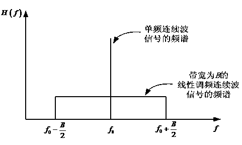
[0101] In this embodiment, the waveform generator generates as Figure 5 The transmission signal of the symmetrical triangular FM continuous wave radar shown, the target echo signal obtained is as follows Figure 5 shown. Figure 5 The solid line in the middle represents the waveform of the transmitting signal, whose frequency changes linearly with time, and the modulation pattern is a symmetrical triangle wave, and the dotted line represents the echo signal waveform of the moving target. Suppose the distance range measured by the speed measuring radar is: 50m-150m, and the speed measurement range is: 10m / s-70m / s. The modulation period of the transmitted signal T r =3ms, carrier start fre...

specific Embodiment approach

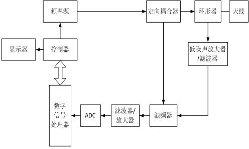
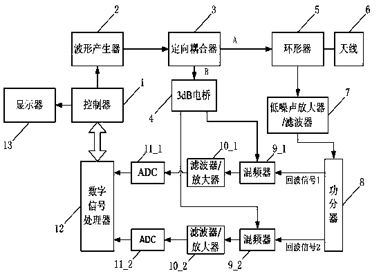
[0106] Figure 9 It is another implementation of the low-interception speed-measuring radar of the present invention. The signal processing part and display control part of the device used in this embodiment are the same as those in Embodiment 1, the difference is that the transmitting signal of this embodiment adopts triangular step FM continuous wave, and the receiving part adopts single-channel reception. The specific implementation of the transmitting part and receiving part is as follows:

[0107] The transmitting part transmits triangular step frequency modulation continuous wave (SFCW), and the generation of triangular SFCW adopts the method of DDS to stimulate PLL, that is, the output signal of DDS is used as the reference signal of PLL. The controller writes frequency control words to DDS and PLL respectively K and phase lock control word M , the control M of the PLL is only written once when the power is turned on, and then the frequency control word of the DDS is...


PUM


Abstract

A low-interception speed measurement method comprises the steps that 1, frequency modulated continuous waves are generated, echo signals of an object with measured speed are received through an antenna, frequency mixing is carried out on the echo signals and B-path signals, and baseband signals are obtained; 2, the baseband signals are converted into digital signals, sampling and zero filling are carried out, FFT is carried out on the rising part of trace frequency, FFT is carried out on the reduction part of return trace frequency after conjugate taking, and frequency spectrums corresponding to positive/negative frequency modulation slopes are obtained; 3, the frequency spectrums corresponding to the positive/negative frequency modulation slopes are subtracted after module taking, the difference value is changed into an absolute value, and an objective frequency spectrum is obtained; 4, whether an object to be detected exists or not is determined, and if the object to be detected exists, the frequency corresponding to two peak value points within the frequency spectrum normalization range is found out in the objective frequency spectrum, and the speed of the object to be detected is worked out. The invention further discloses a low-interception speed measurement radar. The low-interception speed measurement method and radar have the advantage that the probability that the lower-measurement-speed radar is intercepted by a radar detector can be effectively reduced due to the adoption of the frequency modulated continuous waves with low-interception-probability wave forms.

Description

technical field [0001] The invention relates to the technical field of radar, in particular to a low-interception speed measurement method and a speed measurement radar. Background technique [0002] Because of its cheap price, high accuracy, and flexible layout, speed radar has been widely used in highway traffic control and monitoring, and is used by public security traffic control departments as the preferred tool for detecting whether vehicles are speeding. [0003] The existing speed measuring radar adopts the single-frequency continuous wave system, which has the characteristics of a very narrow emission spectrum, and uses the Doppler effect to measure the speed of the target. figure 1 It is an existing single frequency continuous wave speed measuring radar device. In the transmitting part, the controller generates the frequency by controlling the frequency source as f 0 The single-frequency continuous wave and input it to the directional coupler, the directional co...

Claims


Application Information

Patent Timeline
IPC IPC(8): G01S13/58
CPCG01S13/584G01S7/354G01S13/345
Inventor 陈祝明张也薛雄张新旺张晨曦赵龙
Owner UNIV OF ELECTRONICS SCI & TECH OF CHINA
Why Eureka
Try Eureka