
Eureka
For R&D, Eureka makes reading and utilizing patents & technical documents easy.
Eureka AIR
Designed for self-driven R&D workflows. Generate viable solutions, solve complex R&D challenges, empower your innovation with AI.

Eureka Materials
Designed for material experts only. Revolutionize your material R&D, from search, analyze, to developing new materials.

TechResearch
Generate reliable direction feasibility study reports for your R&D in just a few steps.

TechSeek
Discover and master advanced knowledge NOW. Basics, ideas, possibilities, all at once.

TechMind
As an expert in R&D Theories, TechMind can generates customized viable solutions instantly.

TechRisk
Analyze your overall solution with one click, know your potential R&D risks in advance.

TechMonitor
Get weekly tech updates, stay abreast of the latest tech innovations and key insights.
Electronically controlled continuously graded index electro-optic crystal deflector
A graded index of refraction, electro-optical deflection technology, applied in instruments, optics, nonlinear optics, etc., can solve the problems that light waves cannot form diffraction deflection at the same time, and the incident angle has requirements, achieving simple structure, continuously adjustable deflection angle, electrical Good control performance
- Summary
- Abstract
- Description
- Claims
- Application Information
AI Technical Summary
Problems solved by technology
Method used
Image


Examples
specific Embodiment approach 1
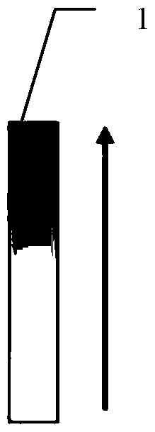
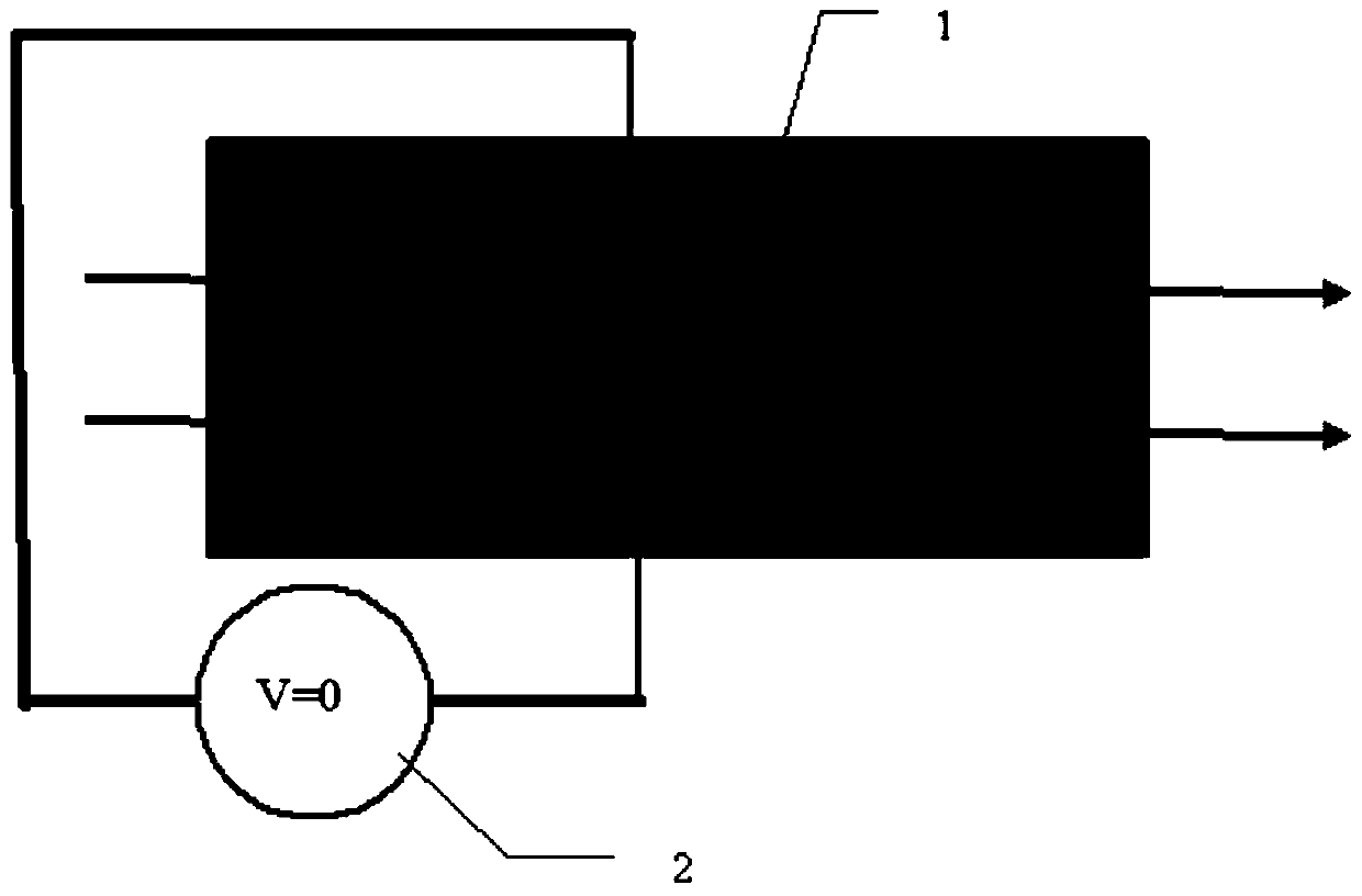
[0038] Specific implementation mode one: the following combination Figure 1 to Figure 6 Describe this embodiment mode, the electro-optic crystal deflector of electronically controlled continuous graded-refractive index described in this embodiment mode is characterized in that it includes an electro-optic deflection crystal 1 and an applied voltage 2,
[0039] The electro-optic deflection crystal 1 is a paraelectric-phase electro-optic crystal, which is obtained by cutting along the growth direction of the paraelectric-phase electro-optic crystal. The paraelectric-phase electro-optic crystal is a crystal whose components are continuously changed along the growth direction grown by the top seed crystal co-solvent method;
[0040] Place the electro-optic deflection crystal 1 in the optical path to be deflected, so that the incident light beam is perpendicular to the surface of the electro-optic deflection crystal 1, the incident direction of the incident light beam is perpendicu...
specific Embodiment approach 2
[0043] Specific embodiment two: This embodiment will further illustrate the first embodiment, the electro-optic deflection crystal 1 is potassium tantalum niobate KTa with a gradient distribution of the secondary electro-optic coefficient 1-x Nb x o 3 Electro-optic crystal, the gradient distribution interval of its quadratic electro-optic coefficient is 0.96×10 -15 m 2 V -2 ~2.70×10 -15 m 2 V -2 , the change range x of the composition niobium Nb along the growth direction is 0.359~0.371.
specific Embodiment approach 3
[0044] Specific implementation mode three: this implementation mode will further illustrate the second embodiment mode, and the electro-optic deflection crystal 1 adopts K 2 CO 3 、 Ta 2 o 5 and Nb 2 o 5 According to the molar ratio of 1.04:0.32:0.68, the raw materials with a total mass of 100g are prepared and grown. The size of the electro-optic deflection crystal 1 in the shoulder growth stage is 11.80mm×11.80mm in the vertical pulling direction, and the cooling rate in the equal diameter growth stage is The temperature is 0.4°C / h, and the gradient distribution of its component niobium Nb is 0.0031 / mm.
[0045] Potassium tantalum niobate KTa in this embodiment 1-x Nb x o 3 , KTN for short; the gradient distribution of the component niobium Nb is 0.0031 / mm, that is, the Curie temperature gradient is 2°C / mm.
[0046] The electro-optic deflection crystal 1 realizes the component distribution by controlling the weight of melted raw materials, the volume of grown crystals...
PUM
| Property | Measurement | Unit |
|---|---|---|
| refractive index | aaaaa | aaaaa |
Abstract
Description
Claims
Application Information
 - R&D Engineer
- R&D Manager
- IP Professional
- Industry Leading Data Capabilities
- Powerful AI technology
- Patent DNA Extraction
Browse by: Latest US Patents, China's latest patents, Technical Efficacy Thesaurus, Application Domain, Technology Topic, Popular Technical Reports.
© 2024 PatSnap. All rights reserved.Legal|Privacy policy|Modern Slavery Act Transparency Statement|Sitemap|About US| Contact US: help@patsnap.com