Silicon steel sheet, iron core linear motor, linear motor platform and LED testing and sorting device

A linear motor, silicon steel sheet technology, applied in sorting, electrical components, electromechanical devices, etc., can solve the problems of motor excitation lag, large motor inductance, etc., and achieve the effect of large load driving capacity

Active Publication Date: 2014-10-01
深圳市宇和创智科技有限公司
View PDF9 Cites 1 Cited by
  • Summary
  • Abstract
  • Description
  • Claims
  • Application Information

AI Technical Summary

Problems solved by technology

[0008] On the other hand, the iron core generally needs to be slotted to embed the coil in the iron core, so the inductance of the motor will be relatively large, and the excitation of the motor will lag behind, and the slotting of the iron core will bring the unique cogging of the iron core linear motor force

Method used


Image

  • Silicon steel sheet, iron core linear motor, linear motor platform and LED testing and sorting device
  • Silicon steel sheet, iron core linear motor, linear motor platform and LED testing and sorting device
  • Silicon steel sheet, iron core linear motor, linear motor platform and LED testing and sorting device

Examples


no. 1 example

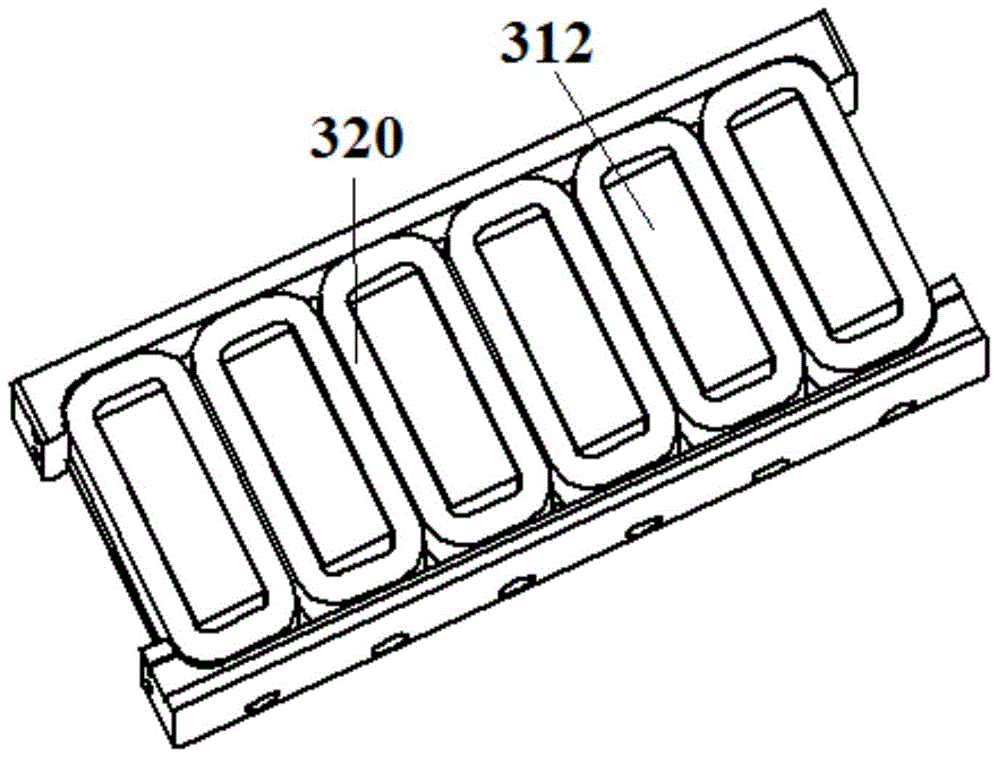
[0043] image 3 A schematic diagram of a core and coil 320 according to a first embodiment of the present invention is shown.

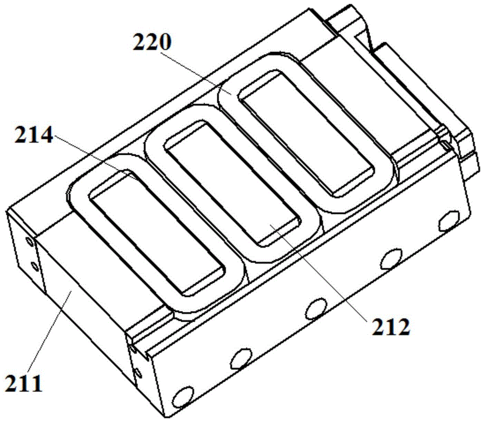
[0044] and figure 2 shown in the core compared to the image 3 Among the teeth of the iron core shown, the side teeth located at the edge ( figure 2 211) in is completely removed, leaving only the centrally located teeth 312 for winding the coil 320 thereon.

[0045] Through experiments and electromagnetic simulation calculations, it is found that the attraction and cogging force between the coil assembly and the magnet assembly can be effectively reduced by removing the side teeth, and the general reduction range is between 10% and 25%. If it is combined with other reduction The method of cogging force, such as magnet tilting, etc., can reduce the cogging force by more than 80%. At the same time, with the removal of the side teeth, the mass of the iron core is also reduced.

[0046] Preferably, the number of middle teeth 312 is an integer multip...

no. 2 example

[0061] Figure 5 A schematic diagram of a core and coil 520 according to a second embodiment of the present invention is shown.

[0062] and figure 2 shown in the core compared to the Figure 5 Of the teeth of the iron core shown, the side teeth 511 located at the edge portion are partially removed. Therefore, the height is lower compared to the centrally located teeth 512 for winding the coil 520 thereon. The height of the side teeth 511 may be about 3 / 4 to about 2 / 3 of the height of the middle teeth 512 .

[0063] Through experiments and simulation calculations, it is found that as long as part of the tooth 511 is cut off, the effect of reducing the attractive force and the cogging force between the coil assembly and the magnet assembly can be achieved. It is known through experiments and simulations that when about 1 / 4 to about 1 / 3 of the side teeth are cut off, sufficient attraction force and cogging force can be reduced. There is a limit to the further reduction in ...

no. 3 example

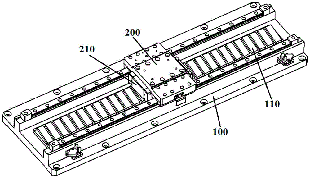
[0075] Figure 7 A schematic diagram of a linear motor platform according to a third embodiment of the present invention is shown.

[0076] Figure 7 The linear motor platform shown includes an X-direction (first) iron-core linear motor located at the lower part and a Y-direction (second) iron-core linear motor located at the upper part.

[0077] The base plate 710 and other components fixed on the base plate 710, such as the X guide rail, the X magnet assembly 720, the X limit switch, the X linear displacement sensor, etc., together constitute the X stator part of the X-direction iron core linear motor. Although the figure schematically shows guide rails, limit switches, linear displacement sensors, etc., in order to avoid obscuring the essence of the present invention, no detailed description is given here.

[0078] An X iron core 740 is installed on the X mover part 730 of the X direction iron core linear motor.

[0079] The Y stator part of the iron core linear motor in...


PUM


Abstract

The invention discloses a silicon steel sheet, an iron core linear motor, a linear motor platform and an LED testing and sorting device. Side teeth of the silicon steel sheet are partially or totally cut off. Correspondingly, an iron core formed by overlaying the silicon steel sheets has not side teeth, or the height of side teeth of the iron core is lower than the height of middle teeth. Through the silicon steel sheet and the corresponding iron core, the tooth trough force of the iron core linear motor is reduced, iron core weight is reduced, and the linear motor platform which is high in speed, high in acceleration and high in precision is realized.

Description

technical field [0001] The invention relates to a silicon steel sheet, an iron-core linear motor, a linear motor platform and LED testing and classification equipment. A plurality of silicon steel sheets are stacked to form an iron core of an iron-core linear motor, and the linear motor platform includes two iron-core linear motors. Background technique [0002] Iron core linear motors have been widely used. [0003] figure 1 is a schematic diagram of an iron core linear motor. [0004] Such as figure 1 As shown, the iron core linear motor includes a stator part 100 and a mover part 200 , and the mover part 200 can move relative to the stator part 100 . [0005] A magnet array 110 is disposed on the stator part 100 . An iron core 210 is disposed on the mover part 200 . Iron core 210 has a plurality of slots ( figure 1 not shown), multiple coils ( figure 1 not shown in ) respectively embedded in these grooves. [0006] figure 2 The iron core 210 and the coil 220 use...

Claims


Application Information

Patent Timeline
Patent Type & Authority Applications(China)
IPC IPC(8): H02K41/02H02K1/34B07C5/00
Inventor 肖俊东
Owner 深圳市宇和创智科技有限公司
Why Eureka
Try Eureka