Flyback switching power circuit

A technology of switching power supply circuit and flyback circuit, which is applied in the direction of high-efficiency power electronic conversion, electrical components, output power conversion devices, etc., can solve the problems of small size, etc., and achieve good protection performance, good EMI performance, and good absorption effect Effect

Active Publication Date: 2014-10-01
MORNSUN GUANGZHOU SCI & TECH
View PDF8 Cites 12 Cited by
  • Summary
  • Abstract
  • Description
  • Claims
  • Application Information

AI Technical Summary

Problems solved by technology

[0033] In view of this, the present invention will solve the deficiencies of the existing flyback switching power supply, and provide a flyback switching power supply that can work at a low temperature of -40°C Circuit, there is no prior art in Figure 4 The capacitor CL is easy to apply, has little influence on the power factor, and has a good absorption effect on the surge voltage. The additional circuit before the rectifier bridge is simple, low in cost, and small in size. At the same time, the differential mode conduction interference meets the CLASS B level in GB9254

Method used


Image

  • Flyback switching power circuit
  • Flyback switching power circuit
  • Flyback switching power circuit

Examples


no. 1 example

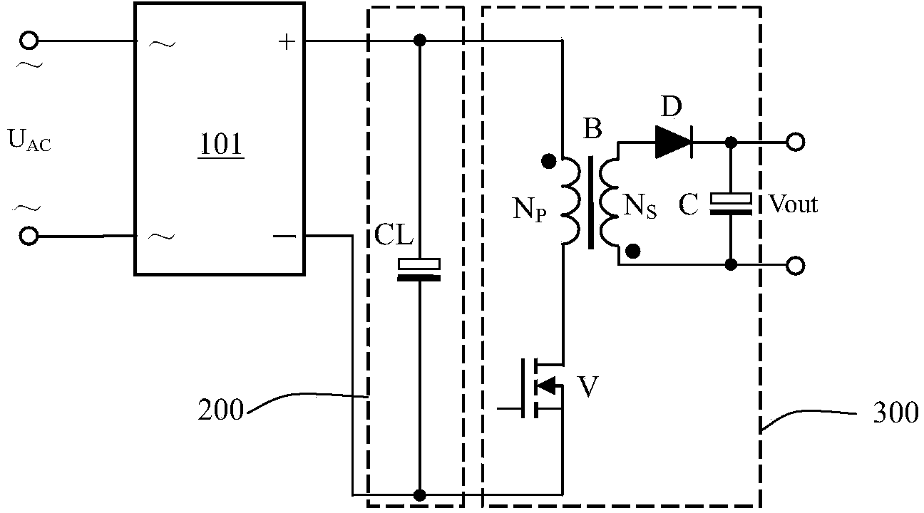
[0061] Figure 5 Shows the schematic diagram of the flyback switching power supply circuit of the first embodiment, a flyback switching power supply circuit for direct connection to the AC input U AC , including a valley filling circuit 203, a rectifier circuit 202 with a protection function located at the front stage of the valley filling circuit, and a flyback circuit 300, the flyback circuit 300 is the same as that in the prior art, see figure 1 The circuit part of the 300:

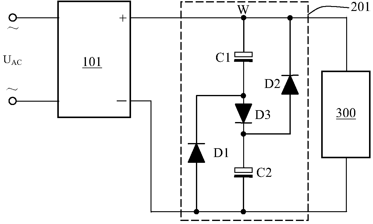
[0062] AC input U AC It has a first terminal O1 and a second terminal O2; it is connected with a rectifier circuit 202 with a protection function, and the rectifier circuit 202 with a protection function includes two interchangeable input terminals, which are Figure 5 The two ends of the first piezoresistor RV1, and the positive output terminal (the V of the rectifier bridge 101 O+ and the terminal connected to the second varistor RV2) and the negative output terminal (the V of the rectifier bridge...

no. 2 example

[0091] Figure 7 It shows the schematic diagram of the flyback switching power supply circuit of the second embodiment, a flyback switching power supply circuit for direct connection to the AC input U AC , including a valley filling circuit 203, and a rectifier circuit 202 with protection function located at the front stage of the valley filling circuit, the AC input U AC It has a first terminal O1 and a second terminal O2, connected to a rectifier circuit 202 with a protection function, and the rectifier circuit 202 with a protection function includes two interchangeable input terminals, which are Figure 7 The two ends of the first piezoresistor RV1, and the positive output terminal (the V of the rectifier bridge 101 O+ and the terminal connected to the second varistor RV2) and the negative output terminal (the V of the rectifier bridge 101 O- and the terminal connected to the second piezoresistor RV2);

[0092] The circuit connection relationship of the valley filling ci...

no. 3 example

[0097] Figure 8 Shows the schematic diagram of the flyback switching power supply circuit of the third embodiment, a flyback switching power supply circuit for direct connection to the AC input U AC , including the valley filling circuit 203 ', and the rectifier circuit 202 with protection function located at the front stage of the valley filling circuit, the AC input U AC It has a first terminal O1 and a second terminal O2, connected to a rectifier circuit 202 with a protection function, and the rectifier circuit 202 with a protection function includes two interchangeable input terminals, which are Figure 8 The two ends of the first piezoresistor RV1, and the positive output terminal (the V of the rectifier bridge 101 O+ and the terminal connected to the second varistor RV2) and the negative output terminal (the V of the rectifier bridge 101 O- and the terminal connected to the second piezoresistor RV2);

[0098] The difference from the first and second embodiments is th...


PUM


Abstract

The invention discloses a flyback switching power circuit. A valley filling circuit is adopted in a filter circuit of the flyback switching power circuit. The work voltage of a capacitor C1 and the work voltage of a capacitor C2 in the valley filling circuit are reduced by a half, -40 DEG C electrolytic capacitor can be adopted, and a third capacitor C3 is in parallel connection to a charging diode D3 in an existing valley filling circuit, so that the withstand voltage of the third capacitor C3 is half of a peak value of input pulse direct current, and high-frequency ripple current of a back switching power 300 can be fully and effectively absorbed. A varistor RV1 and a varistor RV2 are arranged before and behind a rectifier bridge 101, and a thermistor NTC, a safety capacitor X1 and an inductor L form a multi-level two-way filter and protection circuit. The flyback switching power circuit has the advantages that the power factor is high and not affected by a value of the C3, the topological structure of the circuit is simple, the absorption effect on surging voltages is good, cost is low, the size is small, and the difference mode conduction interference degree of the flyback switching power circuit reaches the CLASS B in GB9254.

Description

technical field [0001] The invention relates to the field of switching power supplies, in particular to a high-reliability AC-to-DC switching power supply circuit. Background technique [0002] Industrial and civil uses need to change the AC voltage of various power grids into isolated DC. The very traditional method is to use a large-scale industrial frequency transformer to convert the mains power into low-voltage AC, and then rectify and filter it into DC, and then pass through a linear voltage regulator circuit. To obtain relatively pure direct current, the conversion efficiency of this method is low, the volume is large, and the power factor is relatively low. [0003] The switching power supply that appeared in the 1960s solved this problem better. For example, the current better power supply uses BOOST’s PFC (Power Factor Correction) circuit plus an LLC converter (LLC resonant converter), which can make the power factor It is above 0.95, and the conversion efficiency...

Claims


Application Information

Patent Timeline
Patent Type & Authority Applications(China)
IPC IPC(8): H02M7/04H02M1/32H02M1/42H02M1/14
CPCY02B70/10
Inventor 王保均尹向阳
Owner MORNSUN GUANGZHOU SCI & TECH
Why Eureka
Try Eureka