Supercharge Your Innovation With Domain-Expert AI Agents!

Endoscopy device

A technology of endoscope and lighting department, which is applied in the fields of endoscope, telescope, medical science, etc., and can solve the problems of incapable of precise control of imaging cycle, difficulty, complicated circuit structure, etc.

Active Publication Date: 2014-10-01
OLYMPUS CORP
View PDF9 Cites 4 Cited by
  • Summary
  • Abstract
  • Description
  • Claims
  • Application Information

AI Technical Summary

Problems solved by technology

[0011] However, it is not easy to change the clock frequency of the timing signal for driving the CCD in order to change and control the imaging period of the CCD and the lighting period of the LED in this way. , will also lead to a complex circuit structure, resulting in an expensive system as a whole
[0012] In addition, in the endoscope device described in Japanese Patent Application Laid-Open No. 2007-29746, the imaging cycle of the solid-state imaging device can only be selected from a plurality of predetermined cycles, and fine control of the imaging cycle cannot be performed according to the observation situation.
In addition, if the number of predetermined cycles is increased, the circuit configuration becomes complicated, resulting in an expensive system as a whole.

Method used


Image

  • Endoscopy device
  • Endoscopy device
  • Endoscopy device

Examples


no. 1 approach

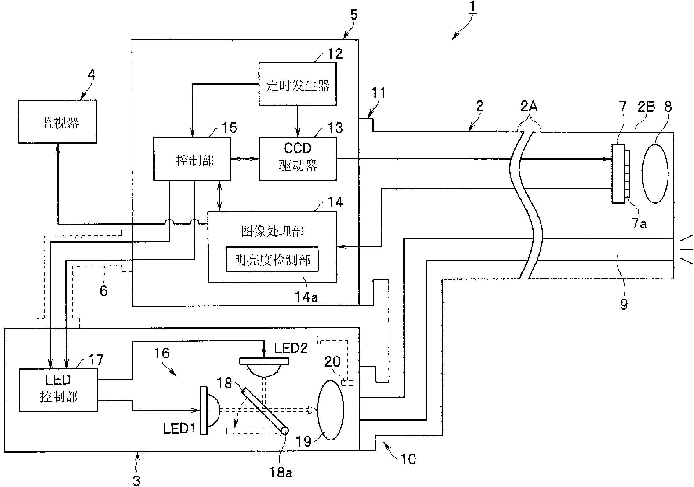
[0026] figure 1 It is a block diagram showing the configuration of the endoscope apparatus according to the first embodiment of the present invention.

[0027] figure 1 The illustrated endoscope device 1 is configured to include: an electronic endoscope (hereinafter referred to as an endoscope) 2 inserted into a body cavity for observing an observation site; and a light source device 3 directed toward the endoscope. 2 provides ordinary light and special light; and a processor 5 performs signal processing on the image signal captured by the endoscope 2 and displays it on the monitor 4.

[0028] The endoscope 2 has: a solid-state imaging device such as a CCD (hereinafter referred to as CCD) 7 as a solid-state imaging device, which is provided on the front end 2B of the insertion part 2A inserted into the body cavity; an objective lens system 8, which is arranged on the front end The front of the CCD 7 of 2B; the light guide 9, which guides the observation illumination light to...

no. 2 approach

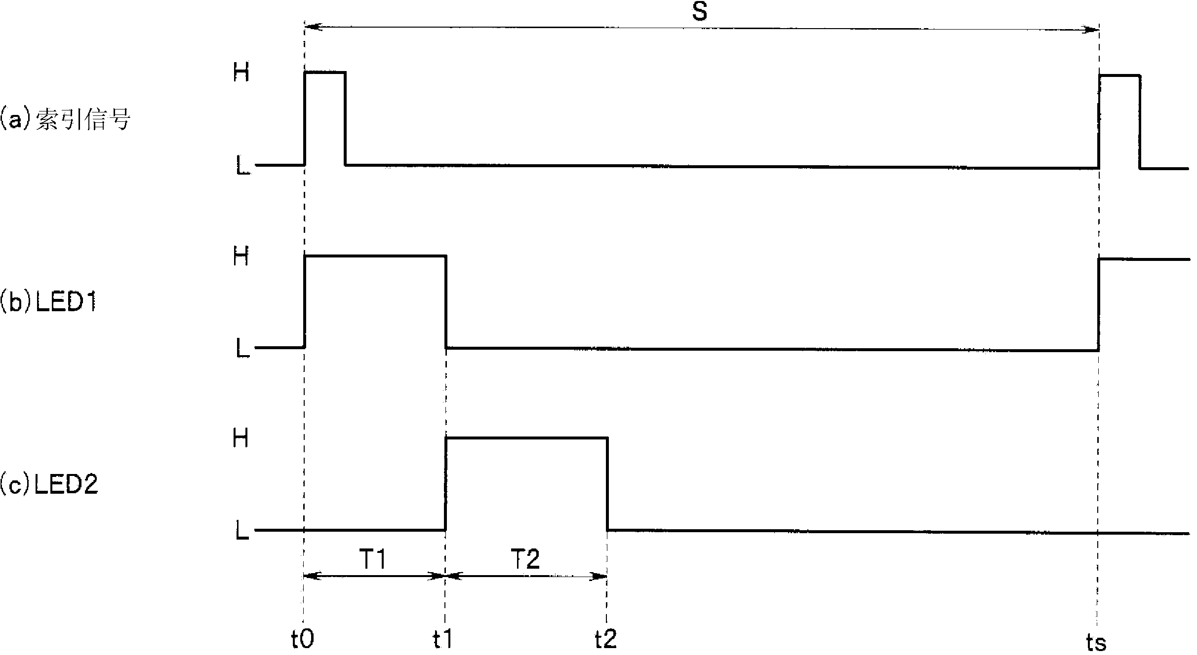
[0083] Figure 4 is a timing chart for explaining the operation of the endoscope device according to the second embodiment of the present invention, Figure 5 It is a timing chart showing a control example of the endoscope apparatus in Modification 2.

[0084] The endoscope device 1 of the present embodiment has the same configuration as that of the above-mentioned first embodiment, but the control method of the LED control unit 17 in the special light observation mode of the light source device 3 is different from the above-mentioned first embodiment.

[0085] That is, in the endoscope apparatus 1 of the present embodiment, the LED control unit 17 controls so that at least two of the plurality of illumination units are driven a plurality of times within the imaging cycle period S.

[0086] Specifically, the LED control unit 17 such as Figure 4 As shown, the lighting period T1 of LED1 and the lighting period T2 of LED2 calculated in advance based on the brightness detection...


PUM


Abstract

An endoscopy device (1) according to one embodiment includes a CCD (7) and an LED control unit (17) (control unit (15)) for controlling an LED (1) and an LED (2). The LED control unit (17) sequentially drives the two LEDs (1), (2) during an imaging cycle (S) of the CCD (7) so that drive times of the LED (1) and the LED (2) do not overlap, on the basis of an imaging start time signal for every imaging cycle (S), and also variably controls the drive times of the LED (1) and LED (2) in order to adjust an amount of light exposure during the imaging cycle (S). The LED control unit (17) also controls at least the initial driving during the imaging cycle (S) of the LED (2), which is driven secondly or later during the imaging cycle (S), so as to be implemented on the basis of the drive timing of the LED (1), which is driven earlier.

Description

technical field [0001] The present invention relates to an endoscope apparatus including a plurality of illumination units that emit illumination light to an observation site, and a control unit that controls driving of the plurality of illumination units. Background technique [0002] As an endoscope device, a so-called electronic endoscope device is generally known. This electronic endoscope device has an illumination unit that emits illumination light. Return light of illumination light reflected by the subject is received (exposed) by a solid-state imaging device such as a CCD (Charge Coupled Device) and photoelectrically converted to obtain an image signal corresponding to an image of the subject. [0003] Among such electronic endoscope devices, a so-called face-sequential type endoscope device is generally known. A surface-sequential endoscope device does not have a light-receiving side color filter in front of a light-receiving element of a solid-state imaging devic...

Claims


Application Information

Patent Timeline
Patent Type & Authority Applications(China)
IPC IPC(8): A61B1/06A61B1/04G02B23/26
CPCG02B26/007G02B23/2469G02B23/2484A61B1/0684A61B1/0669A61B1/0646A61B1/00186A61B1/0638A61B1/045A61B1/043A61B1/0655
Inventor 合渡大和池田吉德
Owner OLYMPUS CORP
Features
  • R&D
  • Intellectual Property
  • Life Sciences
  • Materials
  • Tech Scout
  • Unparalleled Data Quality
  • Higher Quality Content
  • 60% Fewer Hallucinations
Learn More