Ribbon antenna for versatile operation and efficient RF power coupling

A technology for antennas and power supplies, applied to circuits, discharge tubes, electrical components, etc., to achieve the effects of reducing proximity effects, increasing coupling efficiency, and improving performance

Active Publication Date: 2014-10-01
VARIAN SEMICON EQUIP ASSOC INC
View PDF11 Cites 0 Cited by
  • Summary
  • Abstract
  • Description
  • Claims
  • Application Information

AI Technical Summary

Problems solved by technology

Once the plasma is ignited, RF coupling gradually develops into inductive coupling mode (H-mode operation), but some capacitive coupling remains

Method used


Image

  • Ribbon antenna for versatile operation and efficient RF power coupling
  • Ribbon antenna for versatile operation and efficient RF power coupling
  • Ribbon antenna for versatile operation and efficient RF power coupling

Examples


Embodiment Construction

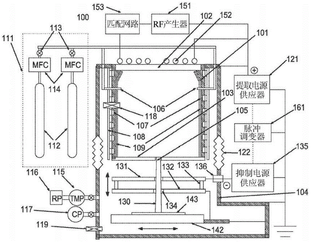
[0029] As mentioned above, typically, the conventional inductively coupled plasma ion source generates plasma based on the energy transfer from the RF power generator to the working gas through the antenna. The power transfer mechanism from the antenna to the plasma is based on Maxwell's third law of electrodynamics:

[0030] ▿ X E → = - ∂ B → ∂ t - - - ( 2 )

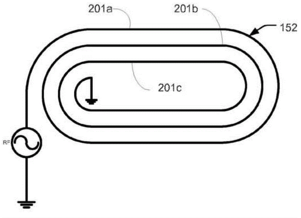
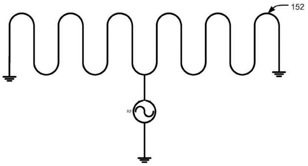
[0031] Electric field induced in plasma Proportional to the magnetic field generated by the antenna Time change, and the magnetic field The temporal change of is proportional to the current flowing through the antenna. Therefore, it is best to have an antenna with very small resistance, because the overall antenna resistance will be small. Generally, RF antennas are constructed with copper pipes. Copper has very good electrical conductivity and thermal conductivity. In addition, it uses pipelines to allow it to be water-cooled. The pipe wall is several millimeters thic...


PUM


Abstract

The invention provides a plasma processing apparatus and method which allow switching between E and H operation modes and also increase the coupling efficiency of the RF power to the plasma. The apparatus may increase plasma density by a factor of about 1.25-1.65 for a given power output. Simultaneously, due to the high efficiency, the need to cool the antenna may be eliminated. A new antenna geometry which increases the amount of surface area for a given volume is used to take advantage of skin effects associated with RF electric current. In some embodiments, the antenna has a single turn to reduce proximity effects. The antenna may also be embedded in a ferrite material to further optimize performance.

Description

Background technique [0001] The plasma manufacturing device generates plasma in a chamber, and this chamber can be used to process a workpiece supported by a platform in a process chamber. In some embodiments, the chamber where the plasma is generated is the processing chamber. The plasma manufacturing apparatus may include a doping system, an etching system, and a deposition system, but is not limited thereto. In some plasma manufacturing devices, such as ion assisted deposition, ions from the plasma are extracted and then directed to the workpiece. In the plasma doping device, the ions can be accelerated to the required energy to produce a certain degree of dopant depth profile in the physical structure of the workpiece, such as a semiconductor substrate. [0002] In some implanters, a plasma for extracting ions can be generated from one chamber, and the workpiece can be processed in a different processing chamber. An example of this type of configuration is a beam line ion i...

Claims


Application Information

Patent Timeline
Patent Type & Authority Applications(China)
IPC IPC(8): H01J37/32
CPCH01J37/32174H01J37/3211
Inventor 科斯特尔·拜洛奎格·钱尼
Owner VARIAN SEMICON EQUIP ASSOC INC
Why Eureka
Try Eureka