Chargeable stick type dust collector and machine body structure applied to same

A charging rod and vacuum cleaner technology, which is applied in the field of charging rod vacuum cleaners, can solve problems such as difficulty, poor dust collection effect, troubles, etc., and achieve the effects of reducing residue, convenient removal and installation, and optimizing dust collection effect

A charging rod and vacuum cleaner technology, which is applied in the field of charging rod vacuum cleaners, can solve problems such as difficulty, poor dust collection effect, troubles, etc., and achieve the effects of reducing residue, convenient removal and installation, and optimizing dust collection effect

CN104083121AInactive Publication Date: 2014-10-08KINGCLEAN ELECTRIC

Image

  • Chargeable stick type dust collector and machine body structure applied to same
  • Chargeable stick type dust collector and machine body structure applied to same
  • Chargeable stick type dust collector and machine body structure applied to same

Examples


Embodiment Construction

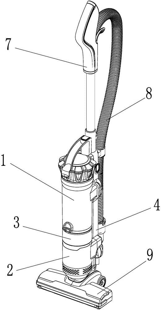
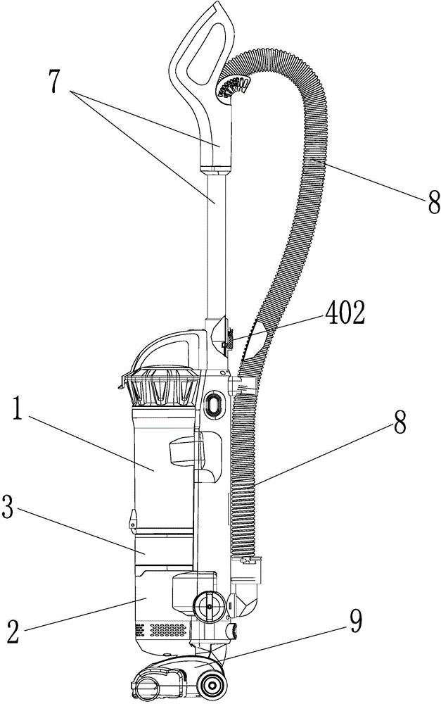
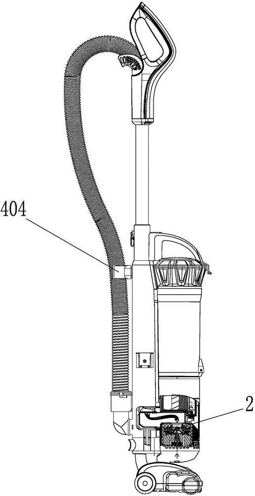
[0034] Figure 1 to Figure 9 A structural schematic diagram of a charging rod vacuum cleaner is shown, which includes a body of the vacuum cleaner, a handle 7 and a hose 8, wherein the hose 8 is connected between the rear end of the handle and the body, and the front end of the handle 7 It is detachably connected with the body.

[0035] The handle 7 mentioned in this example includes figure 1 The approximately "9"-shaped hand grip shown in and the straight rod part connected with the hand grip, such as image 3 and Figure 5 .

[0036] The body of the vacuum cleaner includes a body body 4, a ground brush 9, a multi-stage cyclone 1 (also known as a multi-stage tornado dust cup), a motor 2 and a battery pack 3. Wherein, the floor brush 9 is detachably connected to the bottom of the fuselage body 4, the multi-stage cyclone 1 is detachably connected to the fuselage body 4, and the top of the multi-stage cyclone 1 is provided with a handle 101 to facilitate the multi-stage cycl...


PUM


Abstract

The invention discloses a machine body structure applied to a chargeable stick type dust collector and the chargeable stick type dust collector with the machine body structure. The machine body structure comprises a machine body, a ground brush, a multistage cyclone device, a battery pack and a motor. The multistage cyclone device is located above the motor or the battery pack. The battery pack on the machine body structure can directly provide working power for the pole type dust collector so that dust collection can be more convenient, and the battery pack is convenient to disassemble and assemble so that users can replace the battery pack conveniently.

Description

technical field [0001] The invention relates to the field of vacuum cleaners, in particular to a fuselage structure of a multi-stage tornado charging pole vacuum cleaner and a charging pole vacuum cleaner with the fuselage structure. Background technique [0002] At present, the stick type vacuum cleaners used on the market are generally mainly composed of ground brushes, push rods and handles, wherein the ground brushes and handles are connected to the front and rear ends of the push rods respectively, and the ground brushes are provided with rolling brushes, A small motor that drives the roller brush to rotate, and a dust box for collecting dust. In actual application, the user holds the handle and pushes the vacuum cleaner to move on the ground through the push rod. During the moving process of the vacuum cleaner, the motor runs to drive the roller brush to rotate, thus completely relying on the rotation of the roller brush to sweep the dust on the ground into the accumul...

Claims


Application Information

Patent Timeline
08 Oct 2014
Publication
CN104083121A
IPC
A47L5/12
Inventors
倪祖根