Eureka AIR delivers breakthrough ideas for toughest innovation challenges, trusted by R&D personnel around the world.

Indexing head

An indexing head and gear technology, applied in the field of indexing head, can solve the problems of low indexing accuracy and low indexing efficiency, and achieve the effect of high indexing accuracy and high indexing efficiency

Inactive Publication Date: 2014-10-08
李星
View PDF5 Cites 1 Cited by
  • Summary
  • Abstract
  • Description
  • Claims
  • Application Information

AI Technical Summary

Problems solved by technology

Due to the gap between the teeth in the transmission of the worm gear mechanism in the traditional indexing head, the accuracy of the indexing is not high, and the worm wheel turns a certain angle after several turns of the worm, and the indexing efficiency is low.

Method used


Image

  • Indexing head

Examples


Embodiment Construction

[0017] The principles and features of the present invention will be described below with reference to the accompanying drawings. The examples cited are only used to explain the present invention and not used to limit the scope of the present invention.

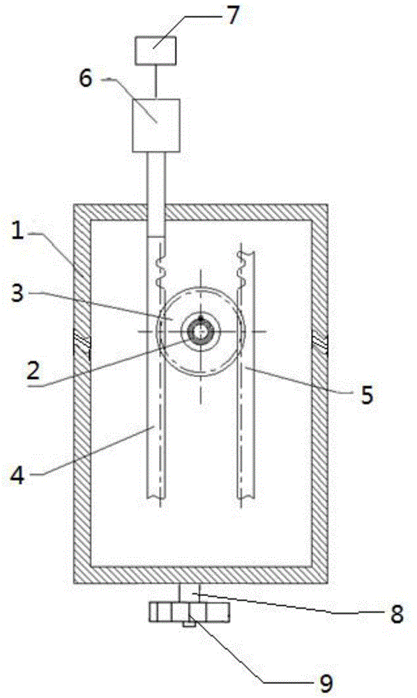
[0018] An indexing head, such as figure 1 As shown, it includes a box body 1, a main shaft 2, a gear 3, a driving rack 4 and a driven rack 5. The main shaft 2, a gear 3, a driving rack 4 and a driven rack 5 are all located in the box 1 Inside, the gear 3 is fixedly connected to the main shaft 2, the driving rack 4 meshes with one side of the gear 3, and the driven rack 5 meshes with the other side of the gear 3.

[0019] The indexing head also includes a driving device 6 located outside the box 1 and connected to one end of the active rack 4.

[0020] The indexing head further includes a motor 7 which is connected to the driving device 6.

[0021] The indexing head also includes a standard 9 and a mandrel 8, and the standard 9 is ins...


PUM


Abstract

The invention relates to an indexing head which comprises a box body, a main shaft, a gear, a driving rack and a driven rack, wherein the main shaft, the gear, the driving rack and the driven rack are all positioned in the box body; the gear is fixedly connected with the main shaft; the driving rack is engaged with one side of the gear; the driven rack is engaged with the other side of the gear. According to the indexing head, the influence on indexing caused by an inter-tooth gap between the gear and the racks is eliminated and the indexing precision is high; a gear and rack engagement form is adopted, the racks move a certain distance, the gear rotates at a corresponding angle, so that the indexing efficiency is high.

Description

Technical field [0001] The invention relates to an indexing head. Background technique [0002] The indexing head is an auxiliary device widely used in metal cutting machine tools such as milling machines, drilling machines, and grinders. It is used to clamp the workpiece and rotate and index the workpiece. The traditional indexing head is mainly composed of a base, a headstock, an indexing disc, an indexing handle, and a spindle. The workpiece is fixed on the chuck and is driven by a worm gear mechanism. The worm gear mechanism is connected to the spindle and finally rotates. The indexing handle performs indexing. In traditional indexing heads, there is a gap between teeth in the transmission of the worm gear and worm mechanism, which results in low indexing accuracy, and the worm rotates a certain angle only after the worm rotates several times, and the indexing efficiency is low. Summary of the invention [0003] The technical problem to be solved by the present invention is ...

Claims


Application Information

Patent Timeline
IPC IPC(8): B23Q16/02B24B47/12
CPCB23Q16/025
Inventor 李星
Owner 李星
Why Eureka
Eureka Blog
Learn More