Current collector frame and overhead crane using the current collector frame

A technology for bridge cranes and collector racks, which is applied in the direction of load hanging components, transportation and packaging, etc. It can solve problems such as affecting coordination, damage to shutdown, and fixing slip lines, etc., to achieve reliable and accurate installation positions, and facilitate assembly and adjustment , the effect of flexible adjustment

Inactive Publication Date: 2016-08-24
HENAN MINE CRANE
View PDF7 Cites 0 Cited by
  • Summary
  • Abstract
  • Description
  • Claims
  • Application Information

AI Technical Summary

Problems solved by technology

At present, the current collector frames commonly used in bridge cranes are non-adjustable structures (see figure 1 As shown), the current collector frame includes a vertical column 101 and a horizontal cantilever 102 fixed on the top thereof. The horizontal cantilever 102 hangs on the left side of the vertical column 101. The overhanging end of the horizontal cantilever 102 is welded with the end of the crane. The mounting frame 103 connected by the beam, and the bottom of the vertical column 101 is fixed with the collector bracket 104 on the left side of the vertical column 101, and the collector 105 is installed on the collector bracket 104. The size is specified according to the user's on-site sliding line, and then welded on site. There are many disadvantages in this assembly method, for example: 1) Since the user's sliding line and track are installed in the entire workshop, there are inevitable errors according to the height and distance of the track surface , often when the middle part is used as the standard for installation, friction, jamming or even damage to the sliding wire and the current collector 105 will occur at both ends. Faults cause equipment damage and shutdown, which seriously affects production and increases equipment maintenance costs; 2) Even if the slide lines and tracks are installed to a very standard, after a period of use, the slide lines, tracks and wheels will all wear out, and the degree of wear different, which will inevitably affect the cooperation between the collector 105 and the sliding wire, and the above problems will also occur in severe cases; 3) On-site production is affected by factors such as the user's site conditions, the technical level of the on-site installation and maintenance personnel, and on-site re-welding and painting. It is often the case that the collector frame of the same equipment is different, and it is difficult to achieve coordination with the host, which seriously affects the appearance and quality; 4) Increases the on-site workload of the installer

Method used


Image

  • Current collector frame and overhead crane using the current collector frame
  • Current collector frame and overhead crane using the current collector frame
  • Current collector frame and overhead crane using the current collector frame

Examples


Embodiment Construction

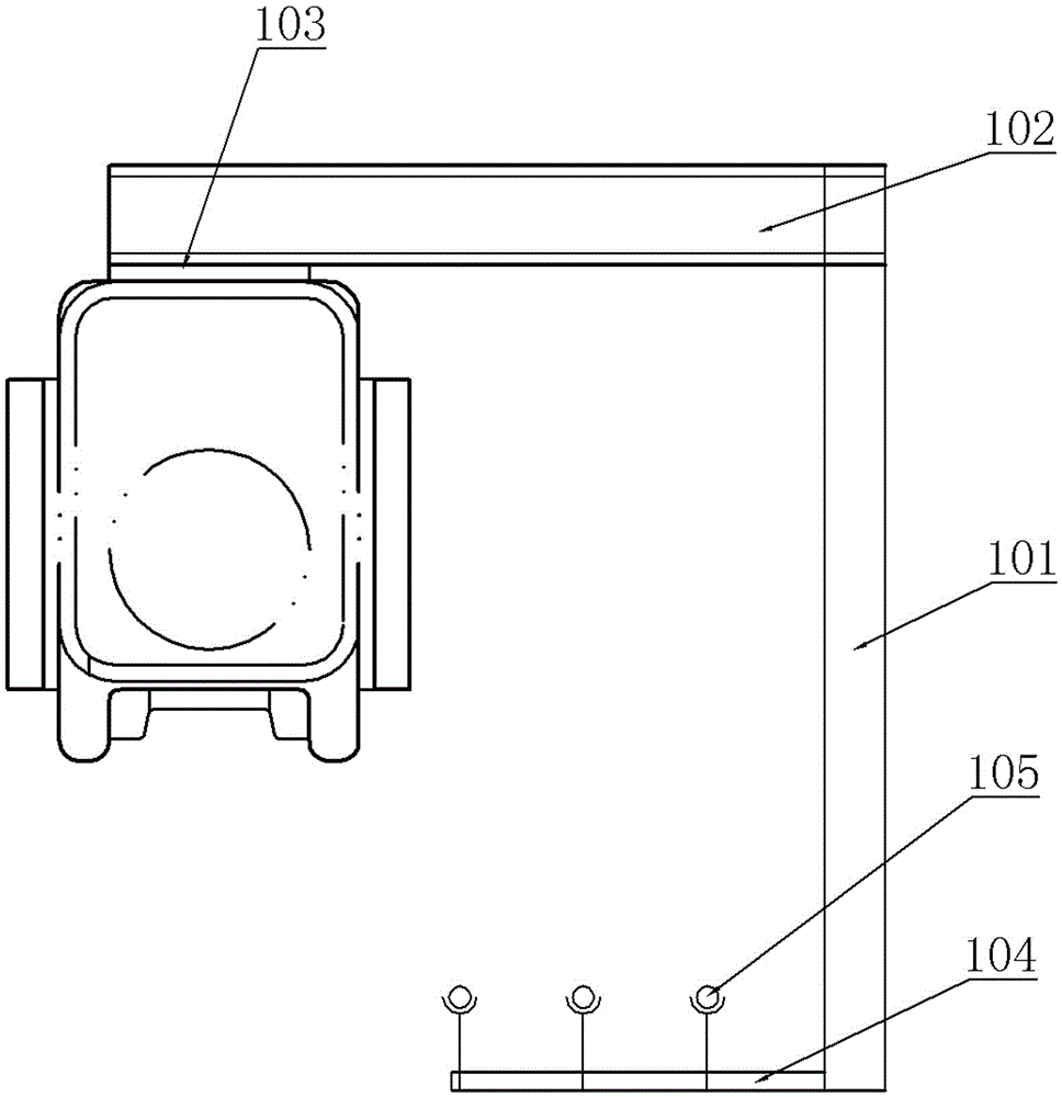
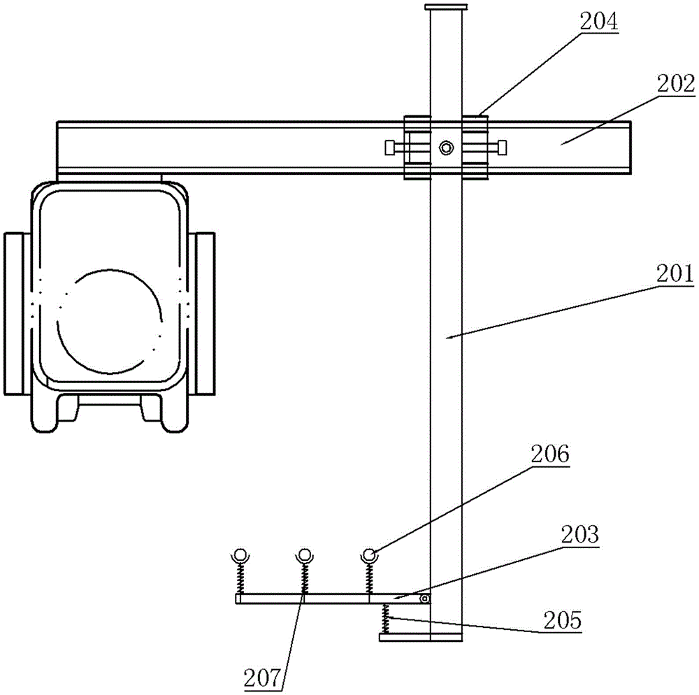
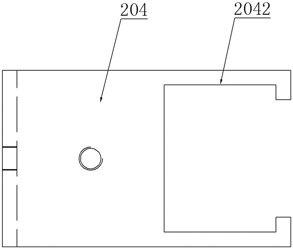
[0023] The embodiment of overhead crane in the present invention: as Figure 2 to Figure 5 As shown, the bridge crane includes an end beam, a collector frame assembled on the end beam, and a collector 206 installed on the collector frame. The collector frame is an adjustable collector frame device for a bridge crane, which includes a vertical guide Frame 201, left and right guide frame 202 and collector bracket 203, left and right guide frame 202 is assembled on the top of vertical guide frame 201 by connector, and connector is the adjustment slip hoop 204 that is assembled on the vertical guide frame 201 outer periphery, adjusts slip hoop 204 is provided with a vertical perforation 2041 for the vertical guide frame 201 to guide and wear up and down, and three locking holes for screwing locking bolts are provided on the hole wall of the vertical perforation 2041, so that the connecting piece can pass through the vertical The perforation 2041 can be lifted and fixed on the vert...


PUM


Abstract

The invention discloses a current collector frame and a bridge crane using the current collector frame. The vertical guide frame in the current collector frame is fixedly equipped with connecting parts, and the left and right guide frames are fixedly mounted on the connecting parts. , and on the left side and / or right side of the vertical guide frame, there are collector brackets for collector installation, and on the left and right guide frames, there are mounting brackets for cooperating with the end beam of the crane. When in use, first put the collector The electrical rack is assembled on the end beam, and the relative positions of the vertical guide frame and the left and right guide frames are adjusted up and down, left and right through the connectors in a large range according to the situation of the sliding wires on site, so that the sliding wires are adjusted to a suitable position, and in the long-term During use, the maintenance personnel can adjust the relative positions of the vertical guide frame and the left and right guide frames again through the connecting piece according to the position change and wear of the collector on the collector frame, so that the collector frame can be conveniently adjusted. Adjust the assembly to reduce the jamming of the collector.

Description

technical field [0001] The invention relates to a current collector frame and a bridge crane using the current collector frame. Background technique [0002] Collector refers to the main device for picking up electric energy on the collector side in the trolley line system. It transmits electric energy directly to the electrical appliances through the sliding foundation of the collector brush and the guide rail, so as to realize the mobile power supply of the system. At present, the current collector frames commonly used in bridge cranes are non-adjustable structures (see figure 1 As shown), the current collector frame includes a vertical column 101 and a horizontal cantilever 102 fixed on the top thereof. The horizontal cantilever 102 hangs on the left side of the vertical column 101. The overhanging end of the horizontal cantilever 102 is welded with the end of the crane. The mounting frame 103 connected by the beam, and the bottom of the vertical column 101 is fixed with...

Claims


Application Information

Patent Timeline
Patent Type & Authority Patents(China)
IPC IPC(8): B66C13/12
Inventor 任海涛高明利
Owner HENAN MINE CRANE
Why Eureka
Try Eureka