Double-material overall pressure filling machine

A pressure filling and dual-material technology, applied in liquid bottling, packaging, bottle filling, etc., can solve the problems of high equipment purchase cost, loss of filling machine manufacturers, large floor space, etc., to reduce equipment purchase cost, The effect of saving filling preparation time and strengthening market competitiveness

Inactive Publication Date: 2014-10-08
常州友联包装设备科技有限公司
View PDF0 Cites 1 Cited by
  • Summary
  • Abstract
  • Description
  • Claims
  • Application Information

AI Technical Summary

Problems solved by technology

[0004] In the existing high-viscosity multi-head filling machine, each filling head needs to be equipped with a feed valve 2, a three-way valve 3, a discharge valve 4 and a hydraulic cylinder 5, and each hydraulic cylinder must be adjusted separately before filling The stroke and initial state of 5 not only waste time but also waste materials in the whole adjustment process. At the same time, because the structure of the three-way valve 3 of each enterprise is different, there are many easily damaged seals in the delivery pipeline. The three-way valve 3 and the seal are often damaged and replaced, increasing the cost
This type of high-viscosity multi-head filling machine has complex structure, high cost, and high after-sales maintenance and repair costs, which not only bring losses to the filling machine manufacturer, but also affect the normal production of the user unit.
At the same time, high-viscosity liquid filling machines are special equipment and are not suitable for filling low-viscosity materials. Packaging companies must be equipped with two filling machines. The material integral pressure filling machine can not only fill high-viscosity materials but also conventional liquids, realizing one machine with multiple functions

Method used


Image

  • Double-material overall pressure filling machine
  • Double-material overall pressure filling machine

Examples


Embodiment 1

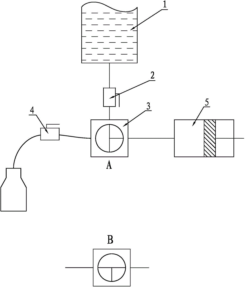
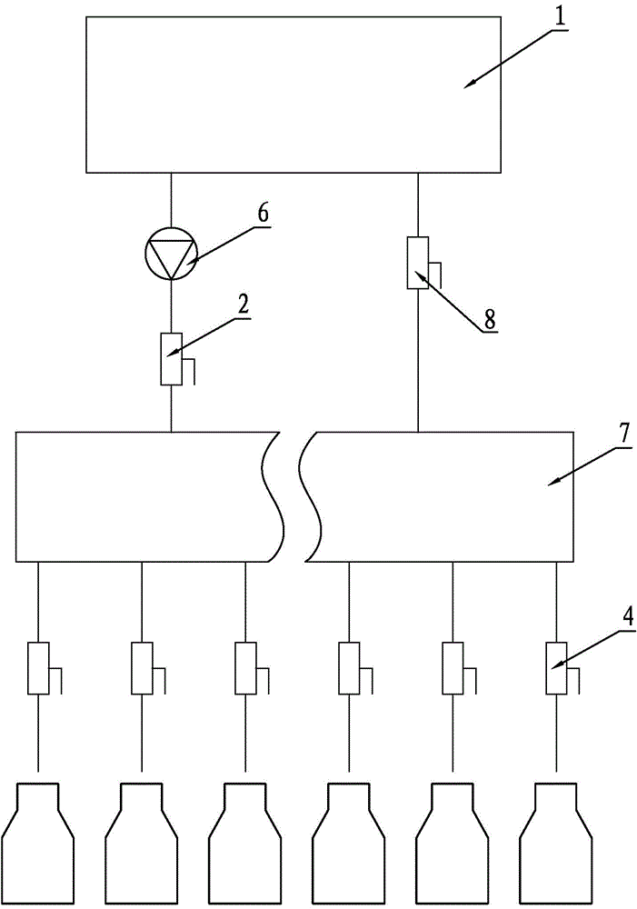
[0017] The present invention is a twelve-head dual-material integral pressure filling machine, and its working principle is as follows: figure 2 As shown, it consists of a material box 1, a feed valve 2, twelve discharge valves 4, a pressure pump 6, a pressure filling container 7 and a normal pressure feed valve 8, the feed valve 2 and the pressure pump 6 are connected in series between the material box 1 and the pressure filling container 7, and the normal pressure feed valve 8 is installed between the material box 1 and the pressure filling container 7, and each filling head passes through the discharge The valve 4 communicates with the pressure filling container 7, and the filling bottle is located directly below the filling head.

[0018] Before filling the high-viscosity liquid, make the feed valve 2 and the normal pressure feed valve 8 in the open state, the discharge valve 4 in the closed state, and start the pressure pump 6. At this time, the pressure pump 6 will put ...

Embodiment 2

[0020] Embodiment 2: In Embodiment 1, the removal of feed valve 2 can also be used, but the flow rate of pressure pump 6 cannot be adjusted.


PUM


Abstract

The invention discloses a double-material overall pressure filling machine which comprises a feed box, a feeding valve, discharging valves, a pressure pump, pressure filling containers and a normal-pressure feeding valve, wherein the pressure pump and the feeding valve are connected in series and then are arranged between the feed box and the pressure filling container; the normal-pressure feeding valve is arranged between the feed box and the pressure filling container; each filling head is communicated with the pressure filling container through the corresponding discharging valve. The double-material overall pressure filling machine achieves multiple purposes, meets the double-material filling requirement and is simple in structure; a three-way valve and a hydraulic cylinder are omitted from each filling head, a ball screw and nut driving mechanism which controls all hydraulic cylinders to synchronously lift is also omitted, and an easily damaged sealing part is absent in a delivery pipeline, so that the cost of the pressure filling machine is greatly reduced, the equipment procurement cost of users is reduced, the occupied area of the filling machine is saved, and the customer subscription degree is high. Moreover, lots of filling preparation time can be saved, and the filling speed can be doubled compared with the filling speed of a conventional filling machine.

Description

Technical field: [0001] The invention belongs to the technical field of liquid filling, and in particular relates to a multi-head multi-type liquid integral pressure filling machine. Background technique: [0002] Liquid filling machines are divided into high-viscosity liquid filling machines and low-viscosity liquid filling machines according to the viscosity of the liquid to be filled. Liquids with different viscosities must be filled with different liquid filling machines. The two are generally not universal. Although the existing high-viscosity liquid filling machines are of different sizes and shapes, most of them use the constant volume method for filling. The working principle is as follows: figure 1 As shown, it includes a material box 1, a feed valve 2, a three-way valve 3, a discharge valve 4 and a hydraulic cylinder 5. The feed port of the three-way valve 3 is connected with the feed valve 2, and the feed valve 2 passes through the feed valve. The pipe is connect...

Claims


Application Information

Patent Timeline
Patent Type & Authority Applications(China)
IPC IPC(8): B67C3/22
Inventor 高志兴
Owner 常州友联包装设备科技有限公司
Why Eureka
Try Eureka