A wood-plastic fence

A fence and wood-plastic technology, applied in fences, building types, buildings, etc., can solve the problems of high cost, high maintenance rate, inconvenient installation, etc., and achieve the effects of low processing cost, low strength and convenient processing.

Active Publication Date: 2016-03-23
山东山禾新材料科技有限公司
View PDF11 Cites 0 Cited by
  • Summary
  • Abstract
  • Description
  • Claims
  • Application Information

AI Technical Summary

Problems solved by technology

In the actual production and use process, the cost is high, the installation is inconvenient, and the maintenance rate is high

Method used


Image

  • A wood-plastic fence
  • A wood-plastic fence
  • A wood-plastic fence

Examples


Embodiment 1

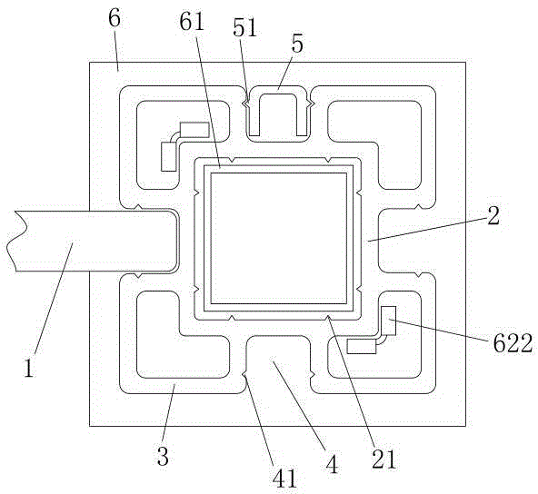
[0032] A wood-plastic fence, comprising a base, uprights installed on the base, a fence 1 arranged between the uprights and whose ends are clamped inside the uprights, the uprights include an inner sleeve 2 and an inner sleeve 2 outside the inner sleeve 2 The outer wall pipe 3, the inner casing is a square pipe, two ribs are respectively provided on the four inner walls of the square pipe, and the outer wall pipe 3 is provided with 4 mounting bars for snapping into the fence 1. Grooves 4, the installation grooves 4 are four corresponding to the central axis of the outer wall of the square tube along the length direction.

[0033] The groove wall of described mounting groove 4 is provided with positioning groove 41, and fence also comprises the sealing strip 5 that can be clamped in mounting groove 4 and is used to fill up mounting groove, and the position corresponding to positioning groove on described sealing strip 5 is provided with For the matching ribs, the positioning gr...

Embodiment 2

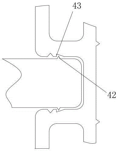
[0041] The difference from the above embodiment is that the part where the end of the fence 1 snaps into the installation groove 4 is provided with a slightly convex clip 42 along the length direction of the column, and the groove wall of the installation groove 4 is provided with a stepped surface facing the inner casing. An outer step 43 for limiting the micro-convex clamping strip.

Embodiment 3

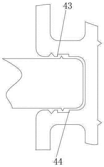
[0043] The difference from the above embodiment is that an inner step 44 is provided on the groove wall of the installation groove 4 opposite to the outer step 43 and close to the inner casing. A buffer groove 45 for limiting the fence is formed between the outer step 43 and the inner step 44, the slightly convex clip 42 is arranged in the buffer groove 45, and the matching rib 51 is arranged in the outer step The outside of platform 43. The depth of the buffer groove 45 is smaller than that of the positioning groove 41 .


PUM


Abstract

The invention belongs to the field of wood-plastic fences, and particularly relates to a novel wood-plastic fence which is firm in clamping connection and convenient to install. The novel wood-plastic fence comprises a base, stand columns and breast boards, wherein the stand columns and the breast boards are installed on the base. Each stand column comprises an inner sleeve and an outer wall tube, wherein the outer wall tube is provided with one or more installation grooves, and a positioning groove is formed in the wall of each installation groove. The novel wood-plastic fence further comprises a sealing bar, wherein the sealing bar is provided with a matching rib. Each positioning groove is formed in the side, close to the opening, of the wall of the corresponding installation groove. Each outer wall tube is fixedly connected with the corresponding inner sleeve through the walls of the corresponding installation grooves. The base comprises a base plate and a positioning tube, wherein clamping plates which press the outer wall surfaces of the inner sleeves or the inner wall surfaces of the outer wall tubes and are used for fixing the stand columns are arranged on the base plate, and each clamping plate comprises a vertical section connected with the base plate and an auxiliary guiding section which is located on the top of the vertical section and is turned outwards. The novel wood-plastic fence is simple in structure and good in installation stability and does not shake easily, the universality of each part is high, machining is convenient, cost is low, waste generated during installation is small, and the integrity of a well installed wood-plastic fence is high.

Description

technical field [0001] The invention belongs to the field of wood-plastic fences, in particular to a wood-plastic fence with firm clamping and convenient installation. Background technique [0002] The existing wood-plastic fence mainly adopts the simple splicing method of the fence and the column or the relatively fixed method of using screws. The former is spliced ​​like building blocks, and the friction between the fence and the column is easy to loosen only by the friction between the contact surfaces. The strength of the fence is low, it is easy to fall apart, and the fence is easy to shake or fall out. The latter is connected by screws, and there are many parts, which is troublesome to connect, disassemble and replace. For example, the application number: 201320414165.4 discloses a wood-plastic fence, including vertical fence slats and horizontal aluminum alloy strips, the horizontal aluminum alloy strips are connected with the vertical fence slats by screws, and the s...

Claims


Application Information

Patent Timeline
Patent Type & Authority Patents(China)
IPC IPC(8): E04H17/16E04H17/20E04H17/22
Inventor 周亮
Owner 山东山禾新材料科技有限公司
Why Eureka
Try Eureka