
Structure of cellular ceramic tube semiconductor heating component

A honeycomb ceramic and semiconductor technology is applied in the structural field of honeycomb ceramic tube semiconductor heating components, which can solve the problems of loose material bonding structure, poor heat dissipation effect of heater, poor mechanical impact resistance, etc., and achieve uniform thermal field. , the material is light and thin, the effect of small thermal inertia

Inactive Publication Date: 2014-10-08
梁卫兵
View PDF6 Cites 0 Cited by
  • Summary
  • Abstract
  • Description
  • Claims
  • Application Information

AI Technical Summary

Problems solved by technology

In addition to the defects of poor heat dissipation, complex structure and poor manufacturability, the heater of this patent also has potential safety hazards such as loosening of the bonded structure of the material after thermal shock, peculiar smell will occur after the temperature rises after the humidity test, and poor mechanical shock resistance. , affected by the structure, it can only be used in the low temperature layer, and the application range is greatly limited;
[0003] Traditional electric heating wires, halogen tubes, etc., due to the small heat dissipation surface, are indirectly conducted with the heated body by other objects. During the electrothermal conversion process, the heat generated by electric energy cannot be quickly transferred to the heated body, resulting in heat on the electric heating element. If it is too concentrated, the element itself will quickly become hot, and a large part of the electric energy will be lost as light energy, resulting in low electric heat conduction efficiency
The general heating wire is always used in a hot state, so it is easy to oxidize, making the resistance thinner and more brittle, and eventually causing an open circuit

Method used


Image

  • Structure of cellular ceramic tube semiconductor heating component

Examples


Embodiment Construction

[0036] The following will clearly and completely describe the technical solutions in the embodiments of the application with reference to the drawings in the embodiments of the application. Apparently, the described embodiments are only some of the embodiments of the application, not all of them. Based on the embodiments in this application, all other embodiments obtained by persons of ordinary skill in the art without creative work fall within the protection scope of this application;

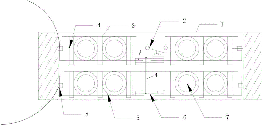
[0037] see figure 1 , the present invention discloses a structure of a honeycomb ceramic tube semiconductor heating element, comprising an electrode 3, a thermal conductor material matrix 7, an insulator 5, a temperature controller 2, a plastic insulator 1, a fixing device 4 and a terminal post 8, the The outer ring of the heat conductor material matrix 7 is an insulator 5, the plastic insulator 1 is arranged on the entire periphery, the temperature controller 2 is arranged in the middle of th...


PUM


Abstract

The invention discloses the structure of a cellular ceramic tube semiconductor heating component. The structure comprises electrodes, thermal conductor material substrates, insulation bodies, a temperature controller, a plastic insulation body, fixing devices and wiring columns, wherein the outer rings of the thermal conductor material substrates are the insulation bodies; the plastic insulation body is arranged at the whole periphery of the structure; the temperature controller is arranged in the whole structure; through holes are formed in corresponding positions between the upper electrodes and the lower electrodes, provided with inner threads and uniformly distributed beside wear-resistant and corrosion-resistant material substrates; through holes are formed in the periphery of the structure and provided with inner threads; the fixing devices penetrate through the through holes to be fixed; the fixing devices at the periphery of the structure are connected with the wiring columns. The structure has the characteristics of simple structure, high efficiency, energy conservation, long life, high comfort level, quick heating, soft heat source, high safety, healthiness, environmental friendliness and capabilities of dissipating heat at low temperature and keeping humidity, and is mainly used for indoor heating.

Description

technical field [0001] The invention belongs to the technical field of electric heating, and in particular relates to a structure of a honeycomb ceramic tube semiconductor heating element. Background technique [0002] The existing electric heater is mainly composed of an electric heating substrate, an electric heating film, a ceramic chassis, and an electrode. For example, the application number is 200910190462.3, and the invention name is a patent application for a new type of ceramic electric heater. A new type of ceramic electric heater , which includes an electric heating substrate, an electric heating film, a ceramic chassis, and electrodes, an electric heating film is attached on the lower plane of the electric heating substrate, electrodes are arranged on the electric heating film, a ceramic chassis is arranged on the lower part of the electric heating film, and the electrodes The electric heating film is drawn out from the ceramic chassis, so that the electric heati...

Claims


Application Information

Patent Timeline
Patent Type & Authority Applications(China)
IPC IPC(8): F24D13/02H05B3/20
Inventor 梁卫兵
Owner 梁卫兵
Features
  • Generate Ideas
  • Intellectual Property
  • Life Sciences
  • Materials
  • Tech Scout
  • Unparalleled Data Quality
  • Higher Quality Content
  • 60% Fewer Hallucinations
Learn More