Relay and arc protection structure thereof

An arc protection and relay technology, applied in relays, electromagnetic relays, electromagnetic relay details and other directions, can solve problems such as poor arc resistance

Active Publication Date: 2014-10-08
XIAMEN HONGFA ELECTRIC POWER CONTROLS
View PDF6 Cites 12 Cited by
  • Summary
  • Abstract
  • Description
  • Claims
  • Application Information

AI Technical Summary

Problems solved by technology

[0010] The purpose of the present invention is to solve the problem of poor arc resistance in the prior art

Method used


Image

  • Relay and arc protection structure thereof
  • Relay and arc protection structure thereof
  • Relay and arc protection structure thereof

Examples


Example Embodiment

[0039] Typical embodiments embodying the features and advantages of the present invention will be described in detail in the following description. It should be understood that the present invention can have various changes in different embodiments, which do not depart from the scope of the present invention, and the descriptions and diagrams therein are essentially for illustrative purposes, rather than limiting this invention.

[0040] The orientations of up, down, top, and bottom mentioned in the present invention are only used to illustrate the relative positional relationship between the components, and do not limit the specific installation orientation of the components in the present invention.
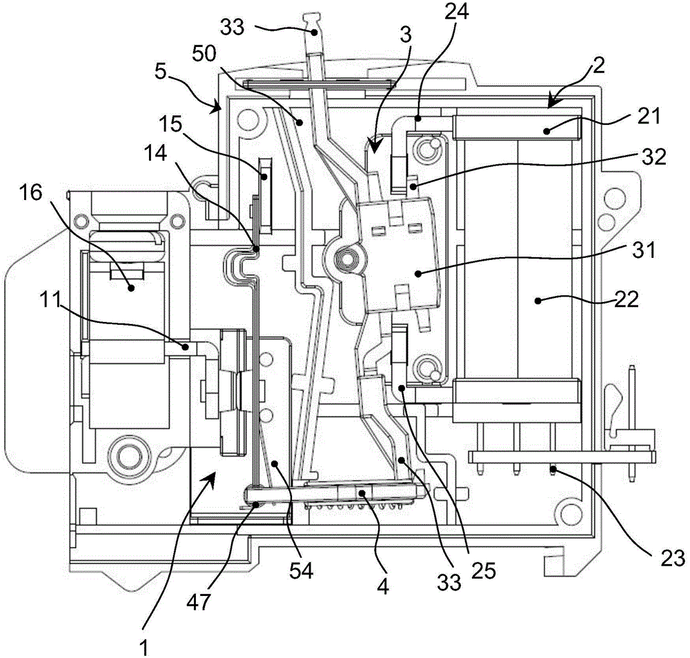
[0041] A high current magnetic latching relay, refer to image 3 , Figure 4 and Figure 5 The relay mainly includes a contact assembly 1, an electromagnetic assembly 2, an armature assembly 3, and a push card 4. These components are all installed in the housing 5. The housing 5 may...


PUM


Abstract

The invention provides a relay and an arc protection structure of the relay. The relay comprises a shell and a contact assembly. The contact assembly comprises at least two lead-out pieces, at least two stationary contacts, at least two movable contacts and a movable reed. The stationary contacts are fixedly installed on the lead-out pieces, and the movable contacts are fixedly installed on the movable reed. The at least two stationary contacts are arranged at certain intervals. A ceramic partition plate is further located between every two adjacent stationary contacts so that the creepage distance between every two contacts can be increased, the voltage withstand performance and the insulation performance of a load output end are improved, and the load capacity of the relay is greatly improved.

Description

technical field [0001] The invention relates to a relay arc protection structure, in particular to a brand new double contact structure relay and its arc protection structure. Background technique [0002] The magnetic latching relay is a new type of relay developed in recent years, and it is an automatic switch. The traditional electromagnetic relay only plays the role of automatically turning on and off the circuit, while the normally open or normally closed state of the magnetic latching relay is completely dependent on the permanent magnet, and the switching state of the relay is triggered by a pulse electric signal with a certain width. Finish. When the contacts of the relay need to be in the open or closed state (that is, when the load is turned on or off), only the positive and negative pulse voltages are used to excite the coil, and the relay completes the switching between the open and closed states in an instant. Usually, when the contact is in the holding state,...

Claims


Application Information

Patent Timeline
IPC IPC(8): H01H9/34H01H50/00
Inventor 张青年钟叔明郭顺可饶丽斌
Owner XIAMEN HONGFA ELECTRIC POWER CONTROLS
Why Eureka
Try Eureka