
Method for achieving environment device monitoring system warning and video monitoring system linkage

A video surveillance system, monitoring system technology, applied in the direction of closed-circuit television systems, etc., to achieve the effects of wide audience, comprehensive and accurate event traceability, and wide application range

Inactive Publication Date: 2014-10-08
兰捷尔智能科技有限公司
View PDF5 Cites 12 Cited by
  • Summary
  • Abstract
  • Description
  • Claims
  • Application Information

AI Technical Summary

Problems solved by technology

[0003] Although the environment and equipment monitoring system can better solve the centralized monitoring and management of equipment or systems, with the advancement of video monitoring systems from analog to digital and the continuous improvement and maturity of video coding and decoding technology, people are no longer satisfied with just You can see the changes, tables or dynamic curves of equipment or system operating status on the monitoring terminal, but hope that when an alarm occurs, you can immediately see and understand the real-time status of the alarm scene (especially fire alarm), so that you can quickly take accurate and effective measures Response measures for maintenance or rescue to minimize impact or loss

Method used


Image

  • Method for achieving environment device monitoring system warning and video monitoring system linkage
  • Method for achieving environment device monitoring system warning and video monitoring system linkage
  • Method for achieving environment device monitoring system warning and video monitoring system linkage

Examples


Embodiment Construction

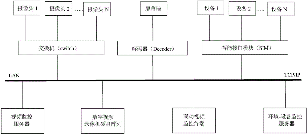
[0048] The functions expected to be realized and the technical principles involved in the method for realizing the linkage between the environmental equipment monitoring system alarm and the video monitoring system of the present invention are as follows:

[0049] 1. Main function description

[0050] ⑴ Equipment alarm and TV monitoring linkage

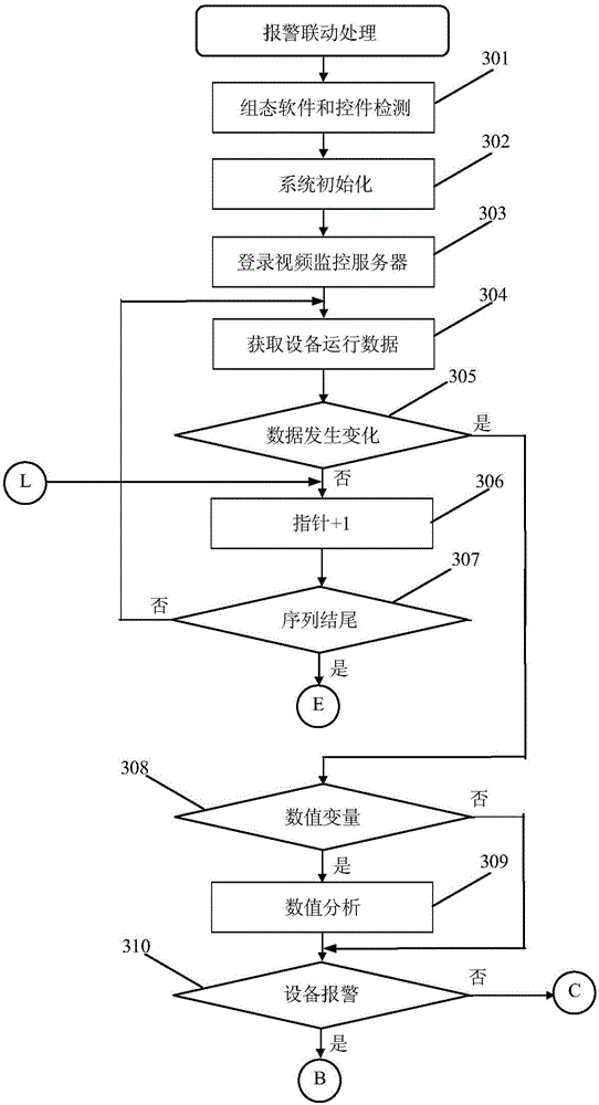
[0051] Through the application program interface function of the environment-equipment monitoring system, real-time monitoring of equipment operating status and data changes, once an alarm occurs, the live video image is immediately switched to the monitoring terminal video window and screen wall, and the time, equipment, Point and other information are written into the log file.

[0052] ⑵Multi-window video display

[0053] Using video window display controls, the screen is divided into several display windows on the monitoring terminal to simultaneously play video images at different monitoring points. In addition, a certain video window ca...


PUM


Abstract

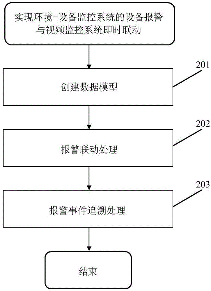
The invention relates to a method for achieving environment device monitoring system warning and video monitoring system linkage. The method comprises a first step of creating a data model for monitoring point locations, decoders and dynamic operation data according to running modes and data structures of an environment device monitoring system and a video monitoring system; a second step of adopting time-sharing operation, performing circulating scanning of all monitoring point locations, obtaining device operation data, and performing system warning linkage processing according to data analysis results; and a third step of finishing single monitoring point location event tracing or multiple monitoring point location event recurrence through operation of selecting warning event table data lines and play windows. According to the method, real-time monitoring of operation data and a warning state of the environment device monitoring system and video channel control management of the video monitoring system can be finished, workers can timely and accurately learn about actual conditions of incident places, and a function of real-time linkage of device and sensor warning and the video monitoring system is achieved.

Description

Technical field [0001] The invention relates to a method for realizing the immediate linkage between the equipment alarm of the environment-equipment monitoring system and the video monitoring system. It belongs to the technical field of monitoring alarm control. Background technique [0002] With the advancement of society and the rapid development of information technology digitization and networking, people have put forward higher requirements for the safe operation of various facilities in large venues and buildings, and the safety of the surrounding environment. Video surveillance systems, power transformation and distribution Monitoring systems, intelligent lighting systems, elevator monitoring systems, automatic fire alarm systems, and safety protection systems have been put into application. As most of the equipment or systems use proprietary communication protocols to achieve internal data transmission, the software architecture uses a closed model, lacking a unified in...

Claims


Application Information

Patent Timeline
Patent Type & Authority Applications(China)
IPC IPC(8): H04N7/18
Inventor 尹惠波李科方向东王立国闫占军
Owner 兰捷尔智能科技有限公司
Learn More