Unlock instant, AI-driven research and patent intelligence for your innovation.

Video coding device and video coding method

A moving image and encoding device technology, which is applied in image communication, digital video signal modification, electrical components, etc., can solve the problems of difficulty in predicting B pictures and deterioration of encoding efficiency, etc.

Inactive Publication Date: 2014-10-08
KK TOSHIBA
View PDF4 Cites 0 Cited by
  • Summary
  • Abstract
  • Description
  • Claims
  • Application Information

AI Technical Summary

Problems solved by technology

Therefore, it is known that in the MPEG-2 standard, since the prediction of the B picture becomes difficult to succeed, the encoding efficiency deteriorates.

Method used


Image

  • Video coding device and video coding method
  • Video coding device and video coding method
  • Video coding device and video coding method

Examples


Embodiment Construction

[0036] Hereinafter, this embodiment will be described with reference to the drawings.

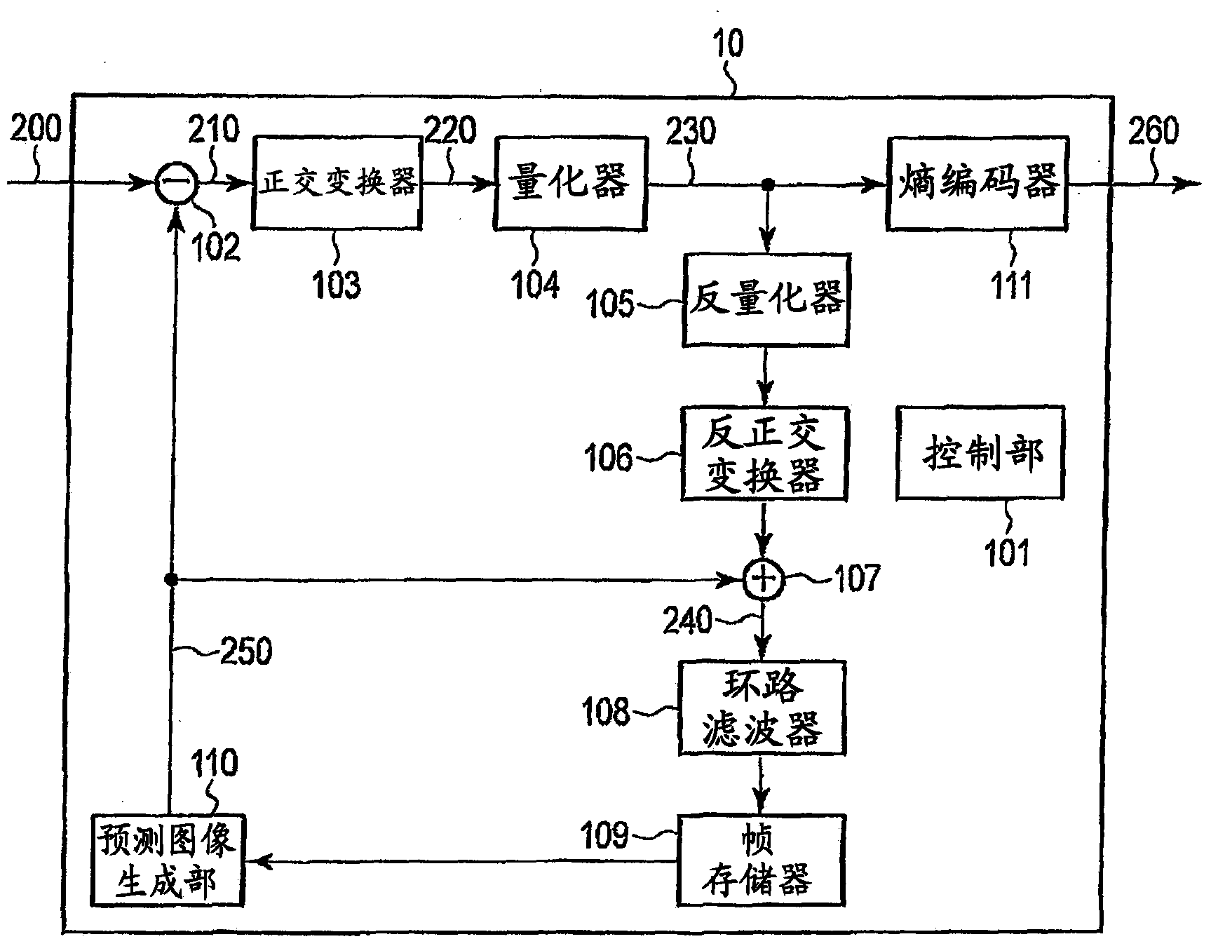
[0037] figure 1 It is a block diagram showing a configuration example of a video encoding device according to an embodiment. The video encoding device 10 is a device for generating an encoded bit stream (encoded data) 260 from an input image signal (image data) 200 . The video encoding device 10 includes a control unit (control unit) 101, a subtractor 102, an orthogonal transformer 103, a quantizer 104, an inverse quantizer 105, an inverse orthogonal transformer 106, an adder 107, a loop filter 108, a frame memory 109 , predicted image generator 110 , and entropy encoder 111 .

[0038] The control unit 101 controls the operation of each element included in the video encoding device 10 .

[0039] The input image signal 200 is externally supplied to the subtractor 102 , and the predicted image signal 250 is also supplied to the subtractor 102 from a predicted image generator 110 described...


PUM


Abstract

Provided are a video coding device and a video coding method that further improve coding efficiency. According to an example of the present invention, the video coding device is provided with a control means. The control means generates B pictures using an inter-picture prediction structure that allows references from reference B pictures in one group of pictures (GOP) to other reference B pictures in the GOP.

Description

technical field [0001] This embodiment relates to a video encoding device and a video encoding method. Background technique [0002] H.264, which is one of video coding methods, can refer to a plurality of reference pictures by introducing DPB (Decoded Picture Buffer). The introduction of DPB contributes to the improvement of coding efficiency in the H.264 standard. Although DPB has a limit on the number of reference pictures due to the upper limit of the size, by using decoded picture marking processing, etc., it can refer not only to pictures that are temporally close to the decoded picture, but also to pictures that are far away. [0003] In addition, in video coding schemes such as H.264, there are I pictures, P pictures, and B pictures. In general, the amount of generated codes decreases in the order of I picture, P picture, and B picture. Therefore, the more B pictures there are, the smaller the code amount of the stream is, and the coding efficiency is improved. ...

Claims


Application Information

Patent Timeline
IPC IPC(8): H04N19/114H04N19/577
CPCH04N19/44H04N19/577H04N19/573
Inventor 川岛裕司菊池義浩
Owner KK TOSHIBA
Features
  • R&D
  • Intellectual Property
  • Life Sciences
  • Materials
  • Tech Scout
  • Unparalleled Data Quality
  • Higher Quality Content
  • 60% Fewer Hallucinations
Learn More