

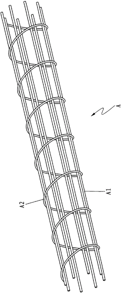
Concrete reinforcing cage forming machine
A technology for concrete reinforcement and forming machines, which is applied in the field of construction machinery, can solve the problems of low production efficiency, high cost of concrete reinforcement cage forming machines, and large floor space, and achieve high production efficiency, increase the pitch adjustment range of stirrups, small footprint effect
- Summary
- Abstract
- Description
- Claims
- Application Information
AI Technical Summary
Problems solved by technology
Method used
Image

Examples
Embodiment Construction
[0018] It should be noted that, in the case of no conflict, the embodiments of the present invention and the features in the embodiments can be combined with each other. The present invention will be described in detail below with reference to the accompanying drawings and examples.
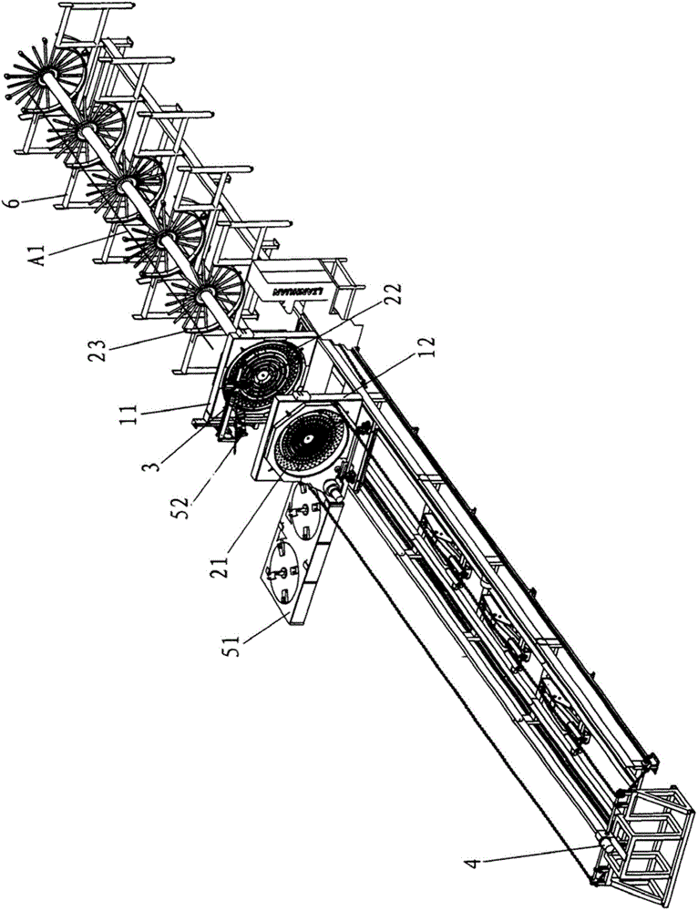
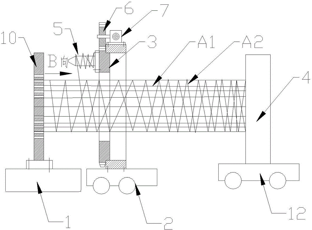
[0019] Such as image 3 and Figure 4 As shown, a preferred concrete reinforcement cage molding machine of the present invention includes a moving frame 4, a rotating frame 3, a fixed frame 1, a stirrup wire releasing device 5, a first moving mechanism 2, a second moving mechanism 12, and a rotating mechanism 7 The first fixed disk 13 is installed on the mobile frame 4, and the second fixed disk 10 is installed on the fixed frame 1, and the circumferential directions of the first fixed disk 13 and the second fixed disk 10 are different radially. A plurality of main reinforcement holes are provided. The first fixed plate 13 is used to fix one end of the main reinforcement A1, and the second fix...
PUM
 Abstract
Description
Claims
Application Information