General assembly table for tank container

A technology of tank container and final assembly platform, which is applied in assembly machines, metal processing equipment, manufacturing tools, etc., can solve the problems of crowded workers, difficulty in improving assembly efficiency, poor working environment, etc., so as to improve the working environment and improve assembly efficiency. , the effect of increasing the space for personnel activities

Active Publication Date: 2014-10-15
NANTONG CIMC TANK EQUIP CO LTD
5 Cites 4 Cited by

AI-Extracted Technical Summary

Problems solved by technology

[0003] The purpose of the present invention is to solve the technical problems in the prior art that the unreasonable layout of the assembly stati...

Method used

1, input and output equipment adopts electro-hydraulic car, has replaced the mode of original driving cylinder hoisting cylinder, has reduced the auxiliary time needed for hoisting, has improved assembly platform production efficiency and safety;
2, the amount of work concentrated on a single station in the prior art is evenly distributed on three station assembly platforms, and the lifting platform can be communicated with the fixed walking platform so that the three station assembly platforms can communicate with each other, by Therefore, the space for personnel activities is increased, and the working environment is improved. In particular, the grinding and matching work station of the overflow box with heavy dust pollution is located at the third assembly station, which is far away from the assembly station of the first station, so that the first station The operation of bit assembly is smoother and more efficient;
3, lifting platform of the present invention adopts the design that one end is fixed, and one end floats, prolongs the service life of lifting platform;
6, the anti-reversal mechanism on the barrel rotation adjustment unit of the present invention adopts a two-way overrunning clutch, compared with the prior art that adopts a temporary welding process screw mandrel on the barrel reinforcement ring to prevent rotation, not only reduces The auxiliary time is reduced, and the secondary grinding caused by the temporary welding process screw rod is eliminated, which affects product quality;
7, the positioning mechanism of the positioning and pressing mechanism of the present invention and the pressing mechanism adopt two independent mechanisms that are provided separately, which improves the accuracy of assembly, reduces the measurement time, and improves the assembly efficiency;
9. The pressing operation of the bottom discharge hole is transferred to the assembly platform. Compared with the completion of the operation on the welding line in the prior art, the manufacturing efficiency of the container is improved, and the logistics is smoother.
A plurality of elevating platforms comprises a first elevating platform 121, a second elevating platform 122, a third elevating platform 123, and a plurality of station assembly platforms comprises a first ...

Abstract

The invention discloses a general assembly table for a tank container. The general assembly table comprises an assembling region, a first working position assembly table, a second working position assembly table, a third working position assembly table, a first lifting platform, a second lifting platform and a third lifting platform, wherein the first working position assembly table, the second working position assembly table and the third working position assembly table are transversely arranged in the assembling region, and the first lifting platform, the second lifting platform and the third lifting platform are arranged corresponding to the first working position assembly table, the second working position assembly table and the third working position assembly table; fixed walking boards are arranged on the two sides of the first working position assembly table, the second working position assembly table and the third working position assembly table, and can be communicated with the first lifting platform, the second lifting platform and the third lifting platform. According to the general assembling platform for the tank container disclosed by the invention, working position intensively concentrated workload in the prior art is distributed to the three working position assembly tables uniformly, and the through fixed walking boards enable the working environment and space of operators to be greatly improved.

Application Domain

Technology Topic

General assemblyWorkload +3

Image

  • General assembly table for tank container
  • General assembly table for tank container
  • General assembly table for tank container

Examples

  • Experimental program(1)

Example Embodiment

[0028] In order to further illustrate the principle and structure of the present invention, the preferred embodiments of the present invention will now be described in detail with reference to the accompanying drawings.
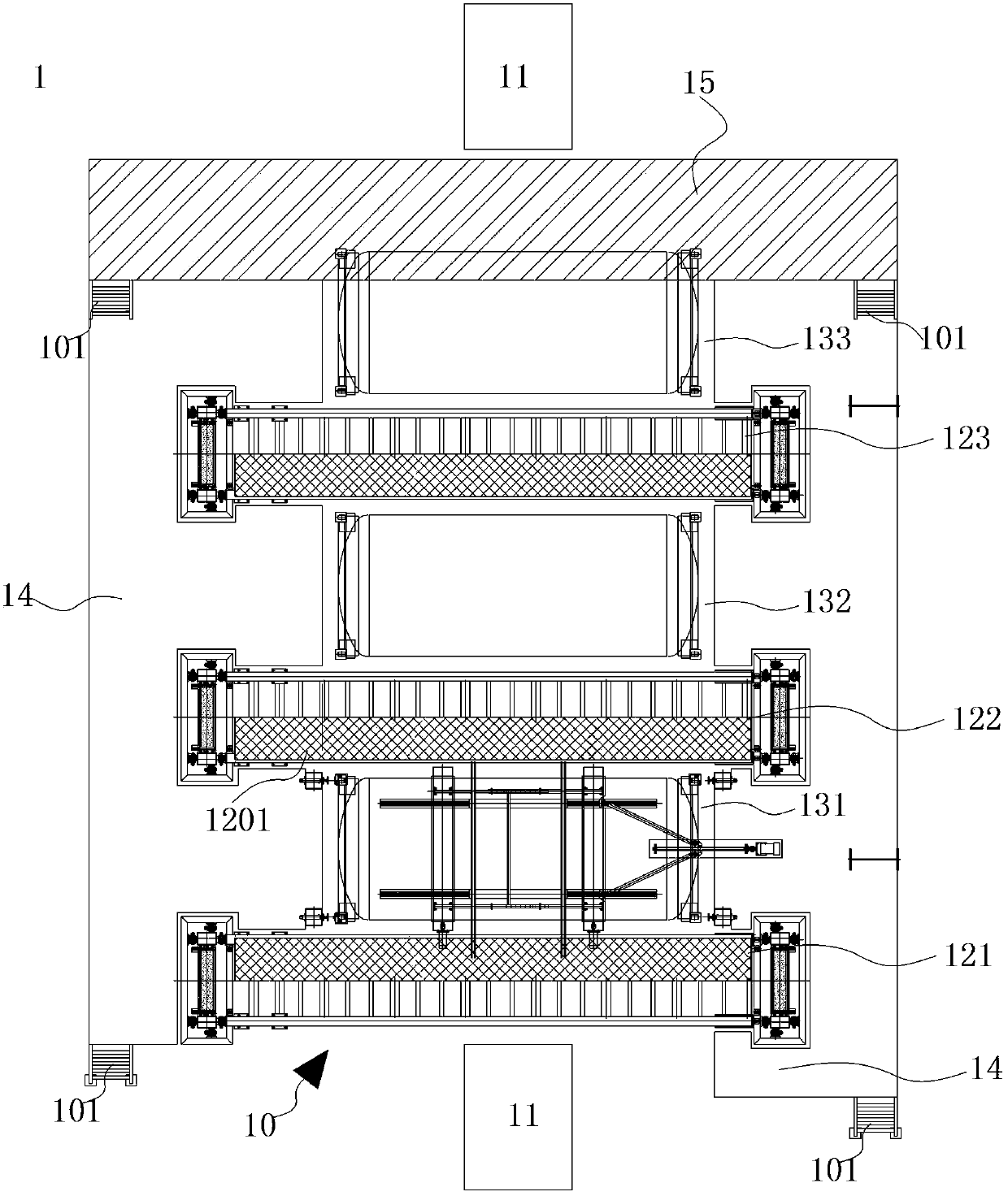
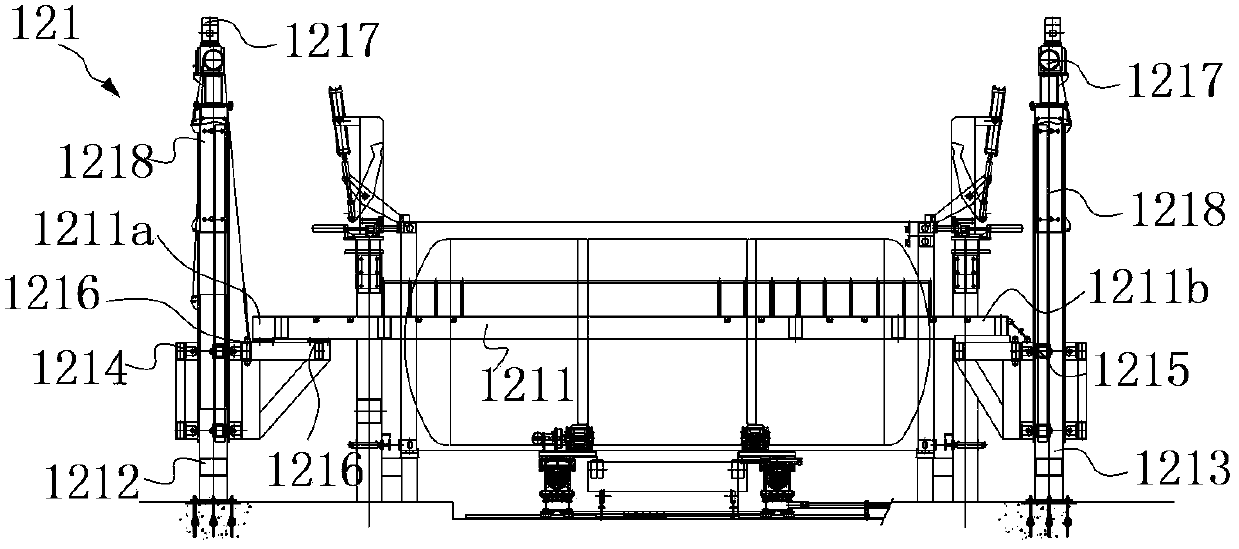
[0029] See figure 1 with figure 2 , figure 1 It is a schematic diagram of the top view structure of the tank container assembly station of the present invention, figure 2 It is a schematic diagram of the side structure of the tank container assembly station of the present invention. The tank container assembly stand 1 of the present invention is used to assemble and weld the cylinder body 31 with end frames, top side beams, bottom side beams and other components according to technical requirements, or directly process the cylinder body 31 itself, for example, overflow Flow box polishing and matching operation, bottom discharge hole profiling operation. The tank container assembly station 1 includes an assembly area 10, a plurality of lifting platforms arranged in the assembly area 10, a plurality of station assembly stations, a fixed platform 15, a fixed platform 14, and a tank for carrying and conveying. The input and output equipment 11 of the barrel 31 of the container.
[0030] The input and output device 11 is an electro-hydraulic vehicle, and the cylinder 31 is placed horizontally above the electro-hydraulic vehicle. The electro-hydraulic vehicle inputs the barrel 31 from the input port at the front end of the assembly area 10 to the corresponding position of the first station assembly station 131 in the assembly area 10, and then the barrel 31 is transferred from the electro-hydraulic vehicle to the first station assembly On the platform 131, after the transfer is completed, the electro-hydraulic car will be removed from the first station assembly station 131. After the first station assembly is completed, the electro-hydraulic car will then transfer the assembled cylinder 31 to the next station assembly station. . According to the above transportation method, the electro-hydraulic vehicle transports the product to the second station assembly station and the third station assembly station for assembly. After the assembly of all stations is completed, the electro-hydraulic vehicle outputs the product from the output port at the back of the assembly area 10. .
[0031] The multiple lifting platforms include a first lifting platform 121, a second lifting platform 122, and a third lifting platform 123. The multiple station assembly stations include a first station assembly station 131 and a second station assembly station 132. , A third station assembly table 133. The first lifting platform 121, the second lifting platform 122, and the third lifting platform 123 are parallel to each other and arranged horizontally in the assembly area 10. The first station assembly station 131, the second station assembly station 132, and the third station assembly station 133 are arranged transversely between the first lifting platform 121 and the second lifting platform 122, between the second lifting platform 122 and the third lifting platform 123, and between the third lifting platform 123 and the fixed platform 15 respectively. The fixed platform 14 extends in the longitudinal direction from both ends of the first lifting platform 121 until it reaches the fixed platform 15. When the lifting platform is raised to the same height as the fixed platform 14, the fixed platform 14 communicates with the lifting platform. The platform 15 can also be connected to the fixed platform 14 through a ladder 101 to form an interoperable general assembly platform that can assemble the three work stations through each other, thereby increasing the activity space of the operators and improving the assembly efficiency. , A top side beam stacking area 1201 and a bottom side beam stacking area 1202 for stacking top side beams and bottom side beams can be respectively arranged above and below each lifting platform to increase the stacking space of parts and improve the utilization rate of space. Here, it should be noted that the first station assembly station 131 is mainly used to complete the assembly work of the overall shape of the tank container 1, such as the positioning and welding of the end frame, the top side beam, the bottom side beam and the cylinder 31 Work, the second station assembly station 132 mainly completes the bottom discharge hole profiling work, and the third station assembly station 133 mainly completes the grinding and matching work of the overflow box.
[0032] See Figure 3a with Figure 3b , Figure 3a In order to show the structure diagram of the first station assembly table and the first lifting platform of the present invention, Figure 3b It is a schematic view of the top structure of the first lifting platform of the present invention. The first lifting platform 121 includes a lifting platform 1211 for the assembly and passage of workers and arranged transversely along the assembly area 10, and a first fixed column 1212, a second fixed column 1213 and a first fixed column 1213 at both ends of the lifting platform 1211. The first lifting carriage 1214 and the second lifting carriage 1215 of the fixed column 1212 and the second fixed column 1213 move up and down. The first end 1211a of the lifting platform 1211 is fixed on the first lifting carriage 1214 by two fasteners 1216, and the second end 1211b is directly placed on the second lifting carriage 1215, so that the second end 1211b is not fixed Floating state. In this embodiment, the two ends of the lifting platform 1211 are respectively fixed at one end and floating at the other end. In the prior art, the structure design with fixed at both ends is generally adopted, but there is a structure design with fixed ends at both ends. Some defects, that is, when the lifting carriage 1211 is raised and lowered, the first lifting carriage 1214 and the second lifting carriage 1215 cannot be completely synchronized, causing the two ends of the lifting carriage 1211 to be in contact with the first lifting carriage 1214 and the second lifting carriage 1214. The frames 1215 interfere with each other and affect the structural stability and service life of the lifting platform 1211, the first lifting sliding frame 1214, the second lifting sliding frame 1215, and the interconnecting parts. The lifting platform 1211 of the present invention is fixed at one end , The floating structure design at the other end just solves the above problems.
[0033] The top ends of the first fixed column 1212 and the second fixed column 1213 are each provided with a power mechanism 1217 for driving the corresponding first lifting slide 1214 and the second lifting slide 1215 respectively along the first fixed column 1212 and the second fixed column 1213. move up and down. The power mechanism 1217 can be a geared motor. The first fixed post 1212 and the second fixed post 1213 are each provided with a counterweight device 1218 that balances and stabilizes together.
[0034] Since the structures of the second lifting platform 122 and the third lifting platform 123 are completely the same as the above-mentioned first lifting platform 121, they will not be repeated here.
[0035] See Figure 4 , Which is a schematic diagram showing the structure of the auxiliary adjustment mechanism of the present invention. When the input and output device 11 transports the cylinder 31 to be processed and assembled to the first station assembly station 131, the cylinder 31 is transferred from the input and output device 11 to the first station assembly station 131 by means of an auxiliary adjustment mechanism 16 . The auxiliary adjustment mechanism 16 includes two lifting mechanisms 161 for temporarily supporting the cylinder 31, two cylinder support roller racks 162, and two cylinder support roller sets 163. The cylinder support roller set 16 is provided on the reinforcement ring 311 of the cylinder 31 The lower part is arranged above the cylinder supporting roller frame 162, and the two lifting mechanisms 161 are respectively arranged at both ends of the cylinder 31. When the input and output device 11 is moved to such as Figure 4 The two lifting mechanisms 161 are raised to lift up the cylinder 31. At this time, the gap between the cylinder 31 and the cylinder support roller frame 162 increases, and the cylinder support roller set 163 is placed in the cylinder Body support roller frame 162, and the cylinder support roller set 163 directly abuts the reinforcement ring 311, the lifting mechanism 161 is lowered, so that the cylinder 31 is lowered onto the cylinder support roller set 163, and the cylinder support roller set 163 supports The barrel 31, at this time, the input/output device 11 can be removed from the first station assembly station 131 to complete the transfer of the barrel 31.
[0036] After the cylinder 31 is transferred to the first station assembly station 131, the position of the cylinder 31 in the four-dimensional direction needs to be adjusted. The corresponding invention is provided with a four-dimensional adjustment mechanism, such as Figure 5a with Figure 5b As shown, Figure 5a In order to show the structure diagram of the four-dimensional adjustment mechanism of the present invention, Figure 5b It is a schematic top view of the longitudinal adjustment unit of the present invention. The four-dimensional adjustment mechanism 17 includes a longitudinal adjustment unit 171, a lateral adjustment unit 172, a height adjustment unit 173, and a cylinder rotation adjustment unit 174.
[0037] The longitudinal adjustment unit 171 includes a driving mechanism 1711, a screw rod 1711 connected to the driving mechanism 1711, a screw nut 1717 matched with the screw rod 1712, connected to the screw nut 1717 and located on both sides of the screw rod 1712 in a figure eight shape Two connecting rods 1713, two linear guides 1714 extending in the longitudinal direction and parallel to each other, a first roller carrier base 1715 and a second roller carrier base 1716 movable along the two linear guides 1714, a first roller carrier base 1715 Connected with two connecting rods 1713, the second roller frame base 1716 is connected with the first roller frame base 1715 through a steel rod 1718. Start the drive mechanism 1711, the drive mechanism 1711 drives the screw 1712 to rotate, the screw nut 1717 is driven by the rotation of the screw 1712 to move linearly along the screw 1712, driving the two connecting rods 1713 to move in the longitudinal direction, thereby driving the first roller frame The base 1715 and the second roller carrier base 1716 move along the linear guide rail 1714 to realize the adjustment of the longitudinal direction of the cylinder 31.
[0038] See Figure 5a with 5c , Figure 5c for Figure 5a A partial enlarged view of area B in the middle. The lateral adjustment unit 172 includes a screw rod 1722, a linear guide 1724, a screw nut 1723 arranged on the screw rod 1722, and a roller carrier base 1725 connected to the screw nut 1723. The screw rod 1722 is connected to the motor, the starter motor, and the screw rod When 1722 rotates, the screw nut 1723 on the screw 1722 moves linearly, and drives the roller carrier base 1725 to move along the linear guide rail 1724 in the lateral direction, thereby realizing the movement of the cylinder 31 in the lateral direction. Such as Figure 5a As shown in the figure, both the B area and the B'area are provided with the lateral adjustment unit 172, and the adjustment units 172 in the B area and the B'area have the same structural features, so they will not be repeated here. When adjusting the position of the cylinder 31 in the transverse direction, the transverse adjustment units in the B area and the B'area can be adjusted simultaneously, or the transverse adjustment units in the two areas can be adjusted separately.
[0039] The above-mentioned lateral adjustment unit 172 is placed above the longitudinal adjustment unit 171. When the longitudinal adjustment unit 171 moves in the longitudinal direction, the entire lateral adjustment unit 172 moves along with the longitudinal adjustment unit 171 in the longitudinal direction, while the adjustment cylinder 31 moves in the transverse direction. In the upper position, the longitudinal adjustment unit 171 is fixed and does not move, and the lateral adjustment unit 172 moves laterally relative to the longitudinal adjustment unit 171.
[0040] Please keep reading Figure 5a , The height adjustment unit 173 is placed on the cylinder support roller frame 1731. The height adjustment unit 173 includes a cylinder support roller frame 1731 and a cylinder support roller set 1732 supported by the cylinder support roller frame 1731. The cylinder support roller set 1732 includes There are at least two rollers, and an adjustable space is formed between the two rollers, and the height of the cylinder 31 can be adjusted by adjusting the distance between the two rollers.
[0041] See Figure 5d , Which is a schematic structural diagram of the cylinder rotation adjustment unit of the present invention. The cylinder rotation adjustment unit 174 is composed of a right angle reduction motor 1741, an anti-reversal mechanism 1742 for preventing the cylinder 31 from rotating freely, an electromagnetic clutch 1743 and a cylinder support roller set 1744 in series in sequence. Start the right-angle reduction motor 1741, the right-angle reduction motor 1741 drives the anti-reverse mechanism 1742 to rotate, the anti-reverse mechanism 1742 drives the electromagnetic clutch 1743 to rotate, and the electromagnetic clutch 1743 drives the cylinder support roller set 1744 to rotate, and then drives the support on the cylinder support roller set 1744 The cylinder 31 rotates to adjust the position of the cylinder 31 in the circumferential direction. The anti-reverse mechanism 1742 is mainly used to prevent the barrel 31 from rotating under the action of its own gravity and caused by non-external force. The anti-reverse mechanism 1742 can be a two-way overrunning clutch. When the right angle reduction motor 1741 starts, the two-way overrunning clutch is engaged , Drives the electromagnetic clutch 1743 to rotate. When the right-angle reduction motor 1741 is turned off, the two-way overrunning clutch is disengaged and the electromagnetic clutch 1743 does not rotate.
[0042] The driving mechanisms of the longitudinal adjustment unit 171, the lateral adjustment unit 172, the height adjustment unit 173, and the cylinder rotation adjustment unit 174 all use electric motors or electric motors to realize the automatic adjustment of the cylinder 31 in the four-dimensional direction.
[0043] Generally, before adjusting the position of the cylinder 31 in the four-dimensional direction, the corner piece needs to be positioned and pressed. Such as Figure 6a As shown, it is a schematic structural diagram of the positioning and pressing mechanism of the corner piece of the present invention. And please refer to Figure 4 The positioning and pressing mechanism 18 includes a positioning device 181 and a pressing device 182. The positioning device 181 includes a positioning block 1811 and an oil cylinder 1812. The piston connecting rod of the oil cylinder 1812 acts on the positioning block 1811 to make the positioning block 1811 abut against the top The angle piece 321 is to ensure the size requirements of the product in the length direction. The pressing device 182 includes a cylinder 1821, a connecting piece 1822, a rotating arm 1823, and a fixing frame 1824. The cylinder 1821 is fixed on the fixing frame 1824, and the connecting piece 1822 Connected to the piston connecting rod of the cylinder 1821, one end of the rotating arm 1823 is movably connected to the connecting piece 1822, and the other end is provided with a pressure head 1825, which can extend into the center hole of the top corner piece 321, and a rotating shaft 1826 passes through The position of the rotating arm 1822 approximately in the middle positions the rotating arm 1823 on the fixing frame 1824, and the rotating arm 1823 can rotate freely around the rotating shaft 1826.
[0044] In addition, in order to make the positioning and pressing mechanism suitable for tank containers of different heights, the positioning and pressing mechanism 18 is also specially provided with an adjusting mechanism 183 for adjusting the height of the positioning and pressing mechanism 18. See Figure 6a with Figure 6b , Figure 6b For the edge Figure 6a A schematic cross-sectional view of the mid-section line AA. The adjustment mechanism 183 includes a guide seat 1831. The positioning mechanism 181 and the pressing mechanism 182 are fixed on the guide seat 1831. The guide seat 1831 includes two side plates 1831b and a vertical plate 1831a, and two side plates 1831b. A guide groove is formed with the vertical plate 1831a. The bolt 1833 passes through the side plate 1831b and a backing plate 1834 located between the side plate 1831b and the guide post 1832 to fasten the guide seat 1831 to the guide post 1832, so that the guide seat 1831 is clamped tightly. On the guide post 1832. When the height of the positioning and pressing mechanism 18 needs to be adjusted, the bolt 1833 is loosened, and driven by external force, the guide seat 1831 together with the positioning mechanism 181 and the pressing mechanism 182 slide up and down along the guide post 1832.
[0045] When the positioning and pressing mechanism 18 is working, first, adjust the adjustment mechanism 183, adjust the positioning mechanism 181 and the pressing mechanism 182 to a height matching the angle piece 321, and then start the oil cylinder 1812, the piston rod extends, and the positioning The block 1811 abuts the corner piece 321, then the cylinder 1821 is activated, the piston rod is extended, and the rotating arm 1823 rotates around the shaft 1826, so that the indenter 1825 extends into the center hole of the corner piece 321 and acts on the cylinder 1821 Next, press the top corner piece 321 against the positioning block 1811.
[0046] In addition, in this embodiment, each corner piece 321 is correspondingly provided with a positioning and pressing mechanism 18 to perform positioning and pressing operations to improve the assembly efficiency.
[0047] After the cylinder 31 completes the assembly work at the first station, it is transferred to the input and output device 11, and then transported from the input and output device 11 to the second station transfer station 132 and the third station assembly station 133 for bottoming respectively. The discharge hole profiling operation and the polishing and matching operation of the overflow box. After all the assembly is completed, the tank container is output from the general assembly platform to complete the general assembly work.
[0048] In summary, the tank container assembly station of the present invention has at least the following advantages:
[0049] 1. The input and output equipment adopts electro-hydraulic vehicles, which replaces the original crane hoisting of the cylinder, which reduces the auxiliary time required for hoisting and improves the production efficiency and safety of the final assembly station;
[0050] 2. The workload that is concentrated on a single station in the prior art is evenly distributed among the three station assembly stations, and the lifting platform can communicate with the fixed platform so that the three station assembly stations can communicate with each other, thereby increasing The space for personnel activities is improved, and the working environment is improved, especially the grinding and matching work station of the overflow box with heavy dust pollution is set at the third assembly station, far away from the first station assembly station, so that the first station assembly Work more smoothly and efficiently;
[0051] 3. The lifting platform of the present invention adopts a design with one end fixed and one end floating, which prolongs the service life of the lifting platform;
[0052] 4. The auxiliary adjustment mechanism adopted by the present invention is convenient and quick, which greatly improves the conversion efficiency of different products;
[0053] 5. When the barrel is adjusted in the four-dimensional direction, it is automatically controlled by the electric control mechanism, which replaces the full manual adjustment method in the prior art, greatly reduces the labor intensity of the operator, and improves the assembly efficiency and automation level;
[0054] 6. The anti-reversal mechanism on the cylinder rotation adjustment unit of the present invention adopts a two-way overrunning clutch, which not only reduces the auxiliary time compared with the method of temporarily welding a screw on the cylinder reinforcement ring to prevent rotation in the prior art , It also eliminates the problem of secondary grinding caused by welding temporary process screw that affects product quality;
[0055] 7. The positioning mechanism and the pressing mechanism of the positioning and pressing mechanism of the present invention adopt two independent mechanisms separately arranged, which improves the accuracy of assembly, reduces the measurement time, and improves the assembly efficiency;
[0056] 8. The adjustment of the positioning and pressing mechanism of the present invention in the height direction is completed by a guide seat that can slide up and down along the guide post. Compared with the prior art method of disassembling and assembling the transition support first, it shortens the time and improves effectiveness;
[0057] 9. Migrate the bottom discharge hole profiling operation to the final assembly station. Compared with the work done on the welding line in the prior art, the manufacturing efficiency of the container is improved and the logistics is smoother.
[0058] The above descriptions are only preferred and feasible embodiments of the present invention, and do not limit the protection scope of the present invention. Any equivalent structure or equivalent process transformation made by using the contents of the description and drawings of the present invention, or directly or indirectly applied to other related technical fields, are similarly included in the scope of patent protection of the present invention.

PUM

no PUM

Description & Claims & Application Information

We can also present the details of the Description, Claims and Application information to help users get a comprehensive understanding of the technical details of the patent, such as background art, summary of invention, brief description of drawings, description of embodiments, and other original content. On the other hand, users can also determine the specific scope of protection of the technology through the list of claims; as well as understand the changes in the life cycle of the technology with the presentation of the patent timeline. Login to view more.

Similar technology patents

Automatic sludge conveying device for pressure filter

Owner:苏州南风优联环保工程有限公司

Coal-rock drift quick tunnelling method

ActiveCN101975066ASuppression of spontaneous angerImprove working environmentTunnelsDrill holeCoal
Owner:河南省煤层气开发利用有限公司

Classification and recommendation of technical efficacy words

Why Eureka
Try Eureka