Method and device for stabilizing well wall in fine managed pressure drilling

It is a technique for managing pressure drilling and stabilizing the borehole wall. It is applied in the direction of wellbore/well components, earthwork drilling and production, etc. It can solve the problems of narrowing, weakening, spraying, leaking, collapse, and sticking of the safe drilling fluid density window, and achieves maintenance The effect of wellbore stabilization

Active Publication Date: 2014-10-15
BC P INC CHINA NAT PETROLEUM CORP +1
View PDF6 Cites 19 Cited by
  • Summary
  • Abstract
  • Description
  • Claims
  • Application Information

AI Technical Summary

Problems solved by technology

Therefore, when drilling in complex formations that are prone to collapse and leakage, wellbore loss may occur within a small range when the bottom hole pressure exceeds the formation pore pressure, and due to the high permeability and conductivity of formation fractures and the weakening of rock strength, Collapse pressure may also occur in a higher range, possibly even higher than the formation pore pressure, a phenomenon that narrows the permissible safe drilling fluid density window
However, in the conventional drilling process, the bottom hole pressure fluctuates in a large range, and it is very easy to cause drilling complications such as blowout, leakage, collapse, and sticking when drilling in such a narrow window formation.

Method used


Image

  • Method and device for stabilizing well wall in fine managed pressure drilling
  • Method and device for stabilizing well wall in fine managed pressure drilling
  • Method and device for stabilizing well wall in fine managed pressure drilling

Examples


Embodiment 1

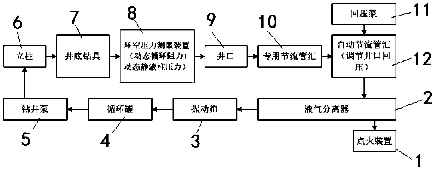
[0022] Embodiment 1: as figure 1 , figure 2 as shown,

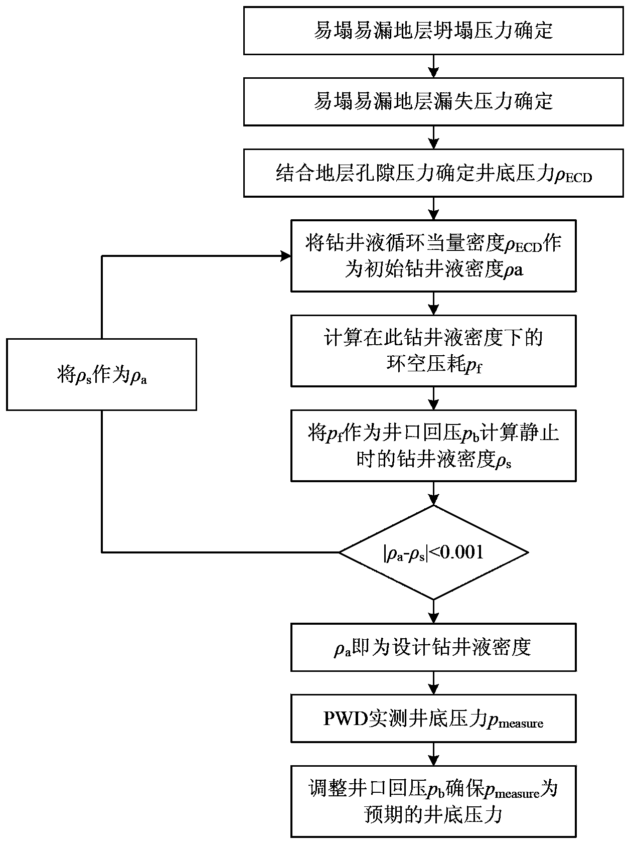
[0023] A kind of fine managed pressure drilling method that the present invention proposes to stabilize the borehole wall, the steps are as follows:

[0024] ①Determine the collapse pressure and leakage pressure of the easy-to-collapse interval;

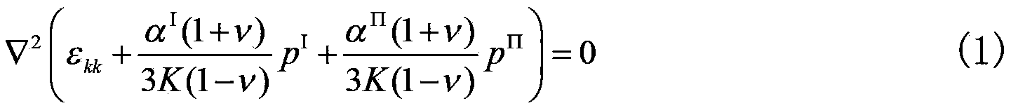
[0025] Combining the dual medium constitutive equation with the stress balance equation and the geometric equation, the formation field equation that is prone to leakage and collapse is obtained.

[0026] ▿ 2 ( ϵ kk + α I ( 1 + v ) 3 K ( 1 - ...

Embodiment 2

[0045] A method for stabilizing the borehole wall of fine managed pressure drilling, comprising the following steps;

[0046] 1. Through the analysis of the collapse and leakage of easy-to-collapse and easy-to-leakage formations, determine the appropriate bottom hole pressure;

[0047] 2. Calculate the actual drilling fluid density;

[0048] 3. Realize the regulation of the bottom hole pressure by controlling the pressure loss of the annular space.

[0049] Due to the existence of highly permeable flow channels, the rocks in formations that are prone to leakage and collapse are highly heterogeneous, and conventional rock mechanics analysis methods are inaccurate.


PUM


Abstract

The invention discloses a method and a device for stabilizing a well wall in fine managed pressure drilling. The method comprises the following steps: analyzing the collapse pressure and the leakage pressure of an easily-collapsing and easily-leaking stratum based on double-porosity elastic hypothesis; designing a proper bottom hole pressure value by comparing the porosity pressure, the collapse pressure and the leakage pressure of the stratum; monitoring an annulus pressure value in real time by using PWD (Pressure While Drilling) in the drilling and pump stopping processes and the processes of pulling out of a hole and running in the hole by combining a drilling fluid density value for circulating pressure loss design so as to ensure that the bottom hole pressure is basically consistent with the designed bottom hole pressure. In the drilling and pump stopping process and the processes of pulling out of a hole and running in the hole, the annulus pressure value is monitored in real time by using the PWD so as to ensure that the bottom hole pressure is basically consistent with the designed bottom hole pressure and no great fluctuation is generated and ensure the stability of the well wall in the drilling operation process. The method and the device disclosed by the invention can be used for keeping the well wall stable in the drilling process of an oil-gas well.

Description

technical field [0001] The present invention relates to a method for calculating the density of drilling fluid and a method for controlling the constant pressure at the bottom of a well to ensure the stability of the well wall in oil and natural gas drilling operations in complex formations that are prone to collapse and leakage, and in particular to a method for stabilizing the well wall in fine controlled pressure drilling And system, establish a system of precise control method of bottom hole pressure for safe drilling in easily collapsed and leaky formations, to ensure safe and fast drilling operations under the condition of narrow drilling fluid density window in complex formations. Background technique [0002] In petroleum engineering, elastic, poroelastic, plastic, and viscoelastic mechanics methods combined with strength criterion methods are widely used to explain wellbore collapse and fracture pressure. According to the rock constitutive relationship, the total st...

Claims


Application Information

Patent Timeline
Patent Type & Authority Applications(China)
IPC IPC(8): E21B49/00
Inventor 王倩周英操陈朝伟项德贵刘玉石马鹏鹏姜英健刘伟罗良波王凯
Owner BC P INC CHINA NAT PETROLEUM CORP
Why Eureka
Try Eureka