High vacuum arc pump and its exhaust unit

A high vacuum and arc technology, applied in vacuum evaporation coating, pumps, mechanical equipment, etc., can solve the problems of collision between electrons and gas molecules, small ionization probability, low density of space gas molecules, and difficulty in achieving effective cooling, etc., achieving huge The effect of instantaneous pumping flow, improving the quality of vacuum products, and eliminating oil vapor pollution

Active Publication Date: 2017-07-25
苏州摩星真空科技有限公司
View PDF8 Cites 0 Cited by
  • Summary
  • Abstract
  • Description
  • Claims
  • Application Information

AI Technical Summary

Problems solved by technology

[0007] 1. In the section where the pressure is ≤10-2 Pa, the density of space gas molecules is very low, electrons collide with gas molecules, and the probability of ionization is very small, so arc discharge cannot be maintained
[0008] 2. Part of the electrons emitted by the titanium target of the arc titanium pump will go around the back of the titanium target and flow into the pump casing panel that fixes the arc pump base. Multiple arc pump bases are usually installed on the pump casing panel. Therefore, it is difficult to achieve effective Cooling, resulting in local heating, releasing a large amount of desorbed gas, reducing the pumping efficiency and ultimate vacuum of the arc titanium pump
[0009] 3. When the cathode target is nearly exhausted, if the new target is not replaced in time, the arc will burn through the cooling water jacket of the arc pump base, resulting in production accidents
[0010]The above shortcomings limit the popularization and application of arc pumps

Method used


Image

  • High vacuum arc pump and its exhaust unit
  • High vacuum arc pump and its exhaust unit
  • High vacuum arc pump and its exhaust unit

Examples


Embodiment 1

[0037] Embodiment one high vacuum arc pump

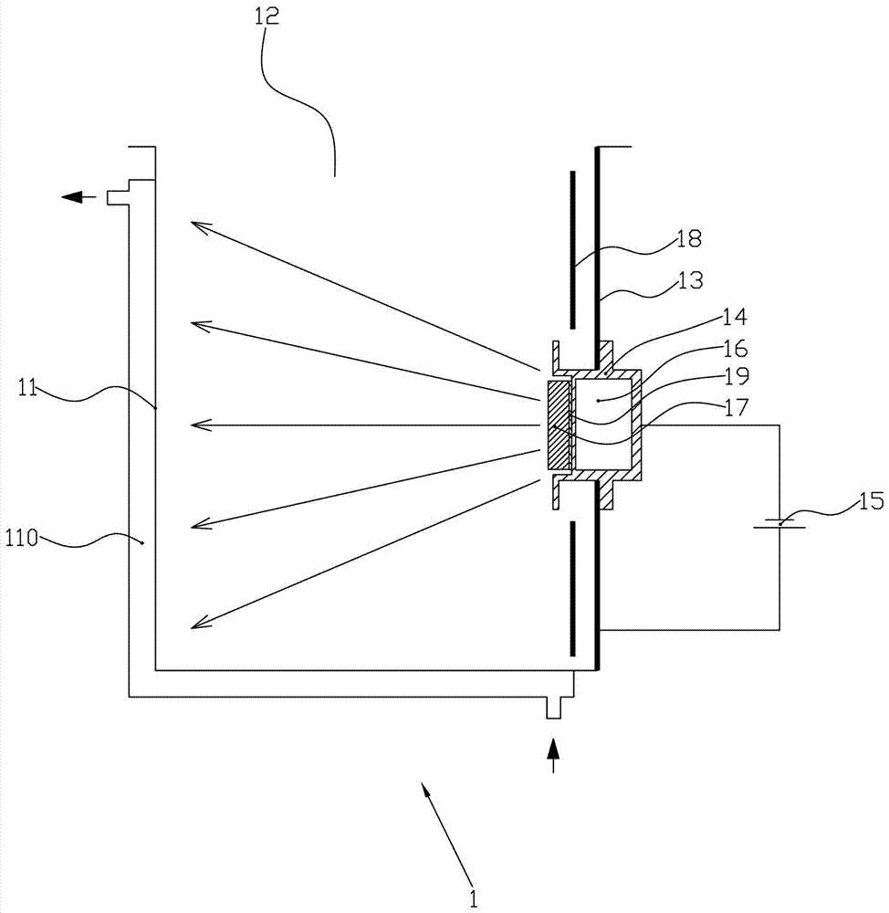
[0038] Such as figure 1 As shown, a high vacuum arc pump 1 provided by Embodiment 1 of the present invention includes a pump casing 11, a pump port 12 is opened on the upper part of the pump casing 11, and an openable panel 13 is located on the right side of the pump casing 11. On the panel 13 A base 14 is fixed, the base 14 is insulated from the panel 13, the base 14 is electrically connected to the negative pole of the power supply 15, a cooling water jacket 16 is provided on the base 14, and cooling water is passed through the cooling water jacket 16 to realize Cooling of the base 14, the inner end of the base 14 is fixedly connected to the cathode target 17, the positive pole of the power supply 15 is electrically connected to the pump casing 11, and the pump casing 11 is also provided with a metal baffle 18 between the cathode target 17 and the panel 13 , The metal baffle 18 is preferably stainless steel or aluminum, and the m...

Embodiment 2

[0045] Embodiment 2 High vacuum arc pump unit

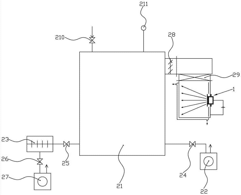
[0046] Such as figure 2 As shown, a high vacuum arc pump unit provided in Embodiment 2 of the present invention includes a vacuum chamber 21, and the vacuum chamber 21 is respectively connected with a roughing pump 22, a traction molecular pump 23, and the high vacuum arc pump as described in Embodiment 1. 1;

[0047] Specifically, the vacuum chamber 21 is connected to the rough pump 22 through the first vacuum valve 24, the vacuum chamber 21 is connected to the drag molecular pump 23 through the second vacuum valve 25, and the drag molecular pump 23 is connected to the backing pump 27 through the third vacuum valve 26. Connected, the vacuum chamber 21 is connected with the high vacuum arc pump 1 through the dust shield 28 and the fourth vacuum valve 29 in turn, the dust shield 28 is preferably an electrostatic dust shield, and the vacuum chamber 21 is also connected with an air release valve 210 and a vacuum gauge 211 respecti...

Embodiment 3

[0054] Embodiment 3 Cryogenic high vacuum arc pump unit

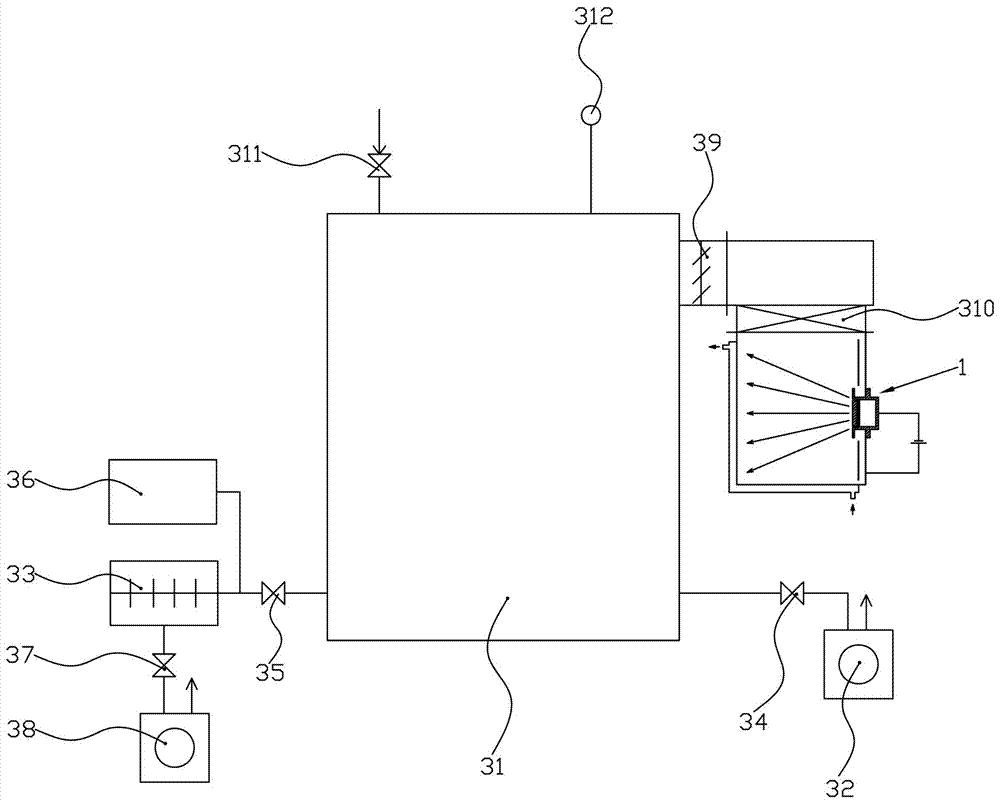
[0055] Such as image 3 As shown, the third embodiment provides a cryogenic high vacuum arc pump unit, including a vacuum chamber 31, the vacuum chamber 31 is respectively connected with a roughing pump 32, a traction molecular pump 33 and the high vacuum arc as described in the first embodiment. pump 1;

[0056] Specifically, the vacuum chamber 31 is connected to the roughing pump 32 through the first vacuum valve 34, and the vacuum chamber 31 is respectively connected to the cryogenic pump 36 and the dragging molecular pump 33 directly or through the second vacuum valve 35, and the dragging molecular pump 33 passes through the third The vacuum valve 37 is connected to the backing pump 38, the vacuum chamber 31 is respectively connected to the high vacuum arc pump 1 through the dust shield 39 and the fourth vacuum valve 310, and the vacuum chamber 31 is also connected to the air release valve 311 and the vacuum gauge ...


PUM

PropertyMeasurementUnit
thicknessaaaaaaaaaa

Abstract

Disclosed are a high vacuum electric arc pump (1), and a high vacuum electric arc pump unit, a cryogenic high vacuum electric arc pump unit, a high vacuum evaporation coating unit and a cryogenic electric arc pump evaporation coating unit comprising the high vacuum electric arc pump, which belong to the field of vacuum production techniques. A high vapour pressure material is doped into a cathode target of a traditional electric arc pump, which substantially extends the high vacuum operating scope of the electric arc pump, and the high vapour pressure material is magnesium, aluminium, zinc or calcium, or a mixture of at least two thereof, and the high vapour pressure material has a weight percentage of 0.5-80% in the cathode target. A metal baffle plate (18) is provided between a cathode target (17) and an openable and closable panel (13) of the electric arc pump (1), and the metal baffle plate (18) is insulated from surrounding components, which eliminates the temperature rise of the panel (13), notably reduces the desorption of an adsorbed gas in the panel (13), and further improves the ultimate vacuum of the electric arc pump (1). In addition, the electric arc pump (1) is provided with a consumption forewarning measure for the cathode target (17), which effectively avoids the accident of burning through a cooling water jacket of the electric arc pump (1), and improves the reliability of the electric arc pump (1).

Description

technical field [0001] The invention belongs to the technical field of vacuum acquisition, and in particular relates to a high-vacuum arc pump and an air pumping unit thereof. Background technique [0002] Patent 201210170072.1 (a pumping system and process) [0003] Patent 201310241954.7 (vacuum furnace exhaust system and its exhaust process) [0004] Patent 201310242244.6 (evaporative coating equipment and its extraction process) [0005] Patent 201310241939.2 (plasma coating equipment and its extraction process) [0006] The above four patents propose an arc pump that uses arc discharge to achieve chemical adsorption pumping (usually using metal titanium as the adsorbent), and its pumping unit, pumping process and typical applications. The arc titanium pump has high pumping speed (it is easy to obtain tens of thousands of L / s high pumping speed), low energy consumption (about 1 / 3 of the traditional diffusion pump), quick start (several seconds to several minutes), and ...

Claims


Application Information

Patent Timeline
Patent Type & Authority Patents(China)
IPC IPC(8): F04B37/14C23C14/56
CPCC23C14/24F04B37/14
Inventor 储继国
Owner 苏州摩星真空科技有限公司
Why Eureka
Try Eureka