Heat insulation pipe shell for LNG (liquefied natural gas) filling station pipeline

A technology for pipeline insulation and gas filling stations, which is applied in the direction of pipeline protection, insulation, and pipeline protection through heat insulation. It can solve the problems of poor insulation effect, increase production cost, and affect insulation effect, etc., and achieve low construction operation difficulty and save energy. Resources, easy and fast disassembly effect

Inactive Publication Date: 2014-10-15
ZHANGJIAGANG SHUNJIA INSULATION TECH
View PDF7 Cites 2 Cited by
  • Summary
  • Abstract
  • Description
  • Claims
  • Application Information

AI Technical Summary

Problems solved by technology

The joint surfaces of these structures are all flat, and it is extremely easy to cause gaps at the joint surfaces during installation, which directly affects the thermal insulation effect
The structure of these shells inevitably encounters the problem of "thermal bridge", that is to say, the heat radiation radiates outward through the gap between the shells and the shells, resulting in heat loss, thus affecting the insulation effect
[0004] In addition, in the prior art, the general insulation shell used in the conveying pipeline is composed of two half-shells with a certain length, the inner surface of the formed shell is in surface contact with the conveying pipeline, the heat dissipation area is large, and the heat preservation effect is not good , and to achieve a certain thermal insulation effect, it is necessary to increase the thickness of the shell, which not only brings inconvenience to the construction, but also increases the production cost

Method used


Image

  • Heat insulation pipe shell for LNG (liquefied natural gas) filling station pipeline
  • Heat insulation pipe shell for LNG (liquefied natural gas) filling station pipeline
  • Heat insulation pipe shell for LNG (liquefied natural gas) filling station pipeline

Examples


Embodiment Construction

[0024] Below in conjunction with accompanying drawing of description, the present invention will be further described.

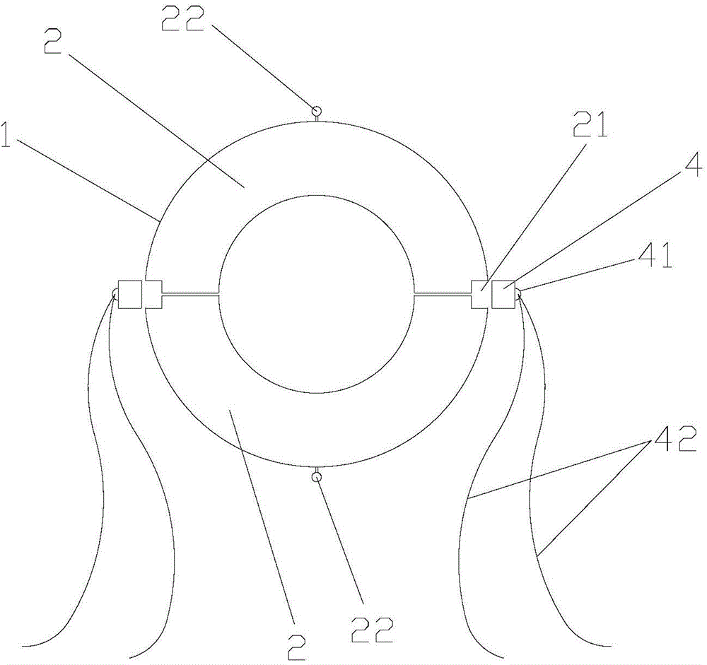
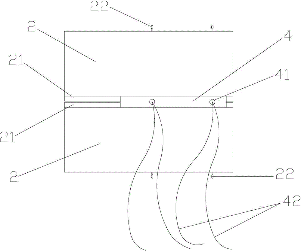
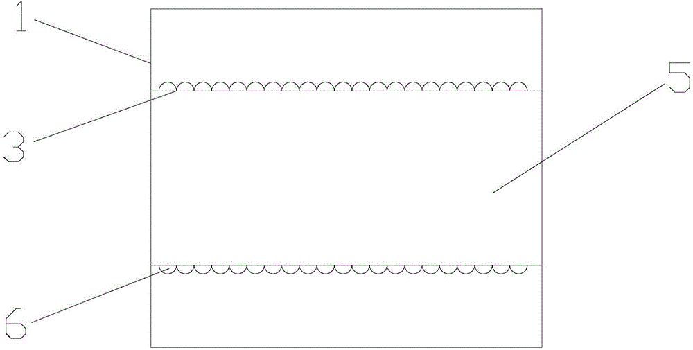
[0025] like figure 1 , figure 2 , image 3 and Figure 4 As shown, a pipe insulation shell of an LNG filling station includes a shell body 1 of a hollow cylindrical structure, and the shell body 1 includes two half-shells 2 with the same structure, and the inner shell of the half-shell 2 The surface 3 is arranged in a wave shape in the axial direction; the outer ends of the two ends of the half-shell 2 are provided with grooves 21; it also includes a filling strip 4, which is concave on the same side as the two half-shells 2 Groove 21 is a strip-like structure of two groove sizes that match.

[0026] The outer surface of the filling bar 4 is provided with a locking ring 41, and the locking ring 41 is connected with a rope member 42 for fixing the two half shells 2; Distributed at intervals in the direction; the rope members 42 are preferably galvanized...


PUM


Abstract

The invention discloses a heat insulation pipe shell for an LNG (liquefied natural gas) filling station pipeline. The heat insulation pipe shell for the LNG filling station pipeline comprises a pipe shell body which is of a hollow cylindrical structure; the pipe shell body comprises two half shells which are of consistent structures; the inner surface of each half shell is in wave-shaped arrangement in the axial direction; grooves are formed in the outside ends of the two end surfaces of each half shell; the heat insulation pipe shell also comprises filling strips; the filling strips are of strip-shaped structures which are matched with the grooves in the same side of the two half shells and are in the same sizes as those of the two grooves; locking rings are arranged on the outer surfaces of the filling strips and are connected with rope pieces used for fixedly connecting the two half shells. The heat insulation pipe shell for the LNG filling station pipeline has the beneficial effects that the structure is simple, the operation is convenient, the practicability is high, more heat can be locked and prevented from dissipating, and the heat is insulated effectively; moreover, the radiating area of the heat insulation pipe shell and a conveying pipeline is small, so that high-efficiency heat insulation is further guaranteed; meanwhile, the heat insulation pipe shell for the LNG filling station pipeline is assembled and disassembled conveniently and quickly; the construction operation difficulty is low; the firmness and the reliability are high; the production cost of the heat insulation pipe shell is also low.

Description

technical field [0001] The invention relates to an auxiliary part for external use of a conveying pipeline, in particular to a pipeline heat preservation shell of an LNG filling station, which belongs to the technical field of pipeline heat preservation. Background technique [0002] Insulation pipelines are widely used in liquid and gas transportation pipe networks. In insulation transportation pipelines, pipeline insulation is a very important link. The success of this link is directly related to whether the pipeline can be officially put into use. [0003] At present, the insulation pipes generally used for LNG filling station pipelines are pipe shell insulation. There are mainly two types of existing heat insulation pipe shells. The tube shell is opened to wrap the tube for installation; the second is to synthesize a circular tube shape from two half-tube shells. Each joint surface of these structures is a plane, and it is extremely easy to cause gaps at the joint surfa...

Claims


Application Information

Patent Timeline
Patent Type & Authority Applications(China)
IPC IPC(8): F16L59/07F16L59/08
CPCF16L59/024F16L59/07F16L59/08
Inventor 邬少忠
Owner ZHANGJIAGANG SHUNJIA INSULATION TECH
Why Eureka
Try Eureka