Thermal insulating pipe shell for liquefied natural gas pipeline

A technology for liquefied natural gas and pipeline insulation, which is applied in the direction of pipeline protection, heat preservation, and pipeline protection through heat insulation. It can solve the problems of unfavorable insulation pipe shell disassembly and reuse, affecting heat preservation effect, and inconvenient construction, so as to improve the reuse rate, Easy to disassemble and easy to install

Inactive Publication Date: 2014-10-15
ZHANGJIAGANG SHUNJIA INSULATION TECH
View PDF7 Cites 3 Cited by
  • Summary
  • Abstract
  • Description
  • Claims
  • Application Information

AI Technical Summary

Problems solved by technology

The joint surfaces of these structures are all flat, and it is extremely easy to cause gaps at the joint surfaces during installation, which directly affects the thermal insulation effect
The structure of these shells inevitably encounters the problem of "thermal bridge", that is to say, the heat radiation radiates outward through the gap between the shells and the shells, resulting in heat loss, thus affecting the insulation effect
[0004] In addition, in the prior art, the insulation tube shell commonly used in the conveying pipeline is composed of two half-tube shells with a certain length. The outer surface of the shell is bound and fixed around the circumference, which not only brings inconvenience to the construction, but also is not conducive to the disassembly and reuse of the heat preservation shell

Method used


Image

  • Thermal insulating pipe shell for liquefied natural gas pipeline
  • Thermal insulating pipe shell for liquefied natural gas pipeline
  • Thermal insulating pipe shell for liquefied natural gas pipeline

Examples


Embodiment Construction

[0023] Below in conjunction with accompanying drawing of description, the present invention will be further described.

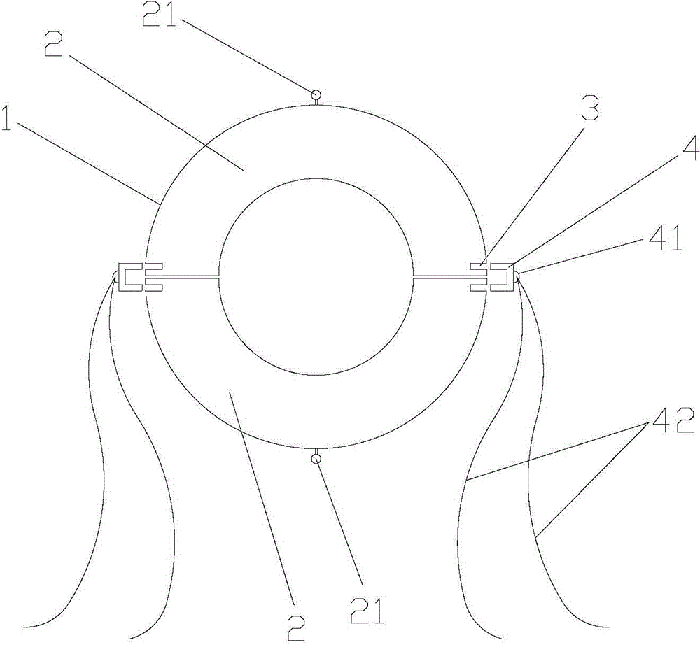
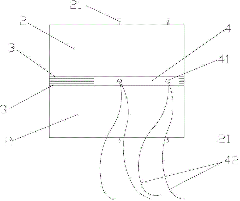
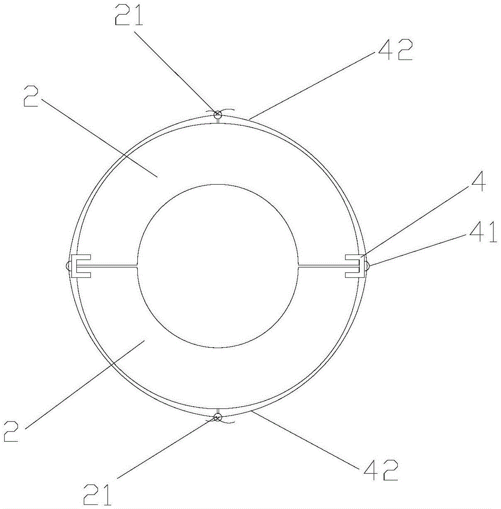
[0024] Such as figure 1 , figure 2 and image 3 As shown, a liquefied natural gas pipeline insulation shell, including a shell body 1 with a hollow cylindrical structure, the shell body 1 includes two half-shells 2 with the same structure, and the outer surface of the half-shells 2 A slot 3 is provided in the axial direction; a filling strip 4 is also included, and the filling strip 4 is a U-shaped structure that is matched and inserted into the slot 3 on the same side of the two half-shells 2 . The slot 3 is parallel to the liquefied natural gas pipeline, that is, the axial directions of the two are consistent.

[0025] The outer surface of the filling bar 4 is provided with a locking ring 41, and the locking ring 41 is connected with a rope member 42 for fixing the two half shells 2; Distributed at intervals in the direction; the rope members 42 are p...


PUM


Abstract

The invention discloses a thermal insulating pipe shell for a liquefied natural gas pipeline. The thermal insulating pipe shell comprises a pipe shell body with a hollow cylinder structure; the pipe shell body comprises two semi shells with consistent structures; insertion slots are arranged on the outer surfaces of the semi shells; the thermal insulating pipe shell also comprises filling strips; the filling strips are of U-shaped structures capable of being inserted into the insertion slots at the same sides of the semi shells; locking rings are arranged at the outer surfaces of the filling strips; the locking rings are provided with rope parts for fixedly connecting the two semi shells; the arc top ends of the cylindrical surfaces of the semi shells are provided with fixing columns for fixing the rope parts. The thermal insulating pipe shell has the advantages of simple structure, convenience in operation and high practicability and can overcome the defect that the heat is radiated to outside by seams between the pipe shells by heat radiation, more heat is locked without dissipation, and the thermal insulating effect is improved; the mounting construction is fast, the manufacturing cost of the pipe shell is low and the firmness and reliability are good.

Description

technical field [0001] The invention relates to an auxiliary part for external use of a conveying pipeline, in particular to a liquefied natural gas pipeline insulation shell, which belongs to the technical field of pipeline insulation. Background technique [0002] Insulation pipelines are widely used in liquid and gas transportation pipe networks. In insulation transportation pipelines, pipeline insulation is a very important link. The success of this link is directly related to whether the pipeline can be officially put into use. [0003] At present, the insulation pipes generally used for liquefied natural gas pipelines are pipe shell insulation. There are mainly two types of existing heat insulation pipe shells. Open and wrap the tube for installation; the second is to synthesize a round tube from two half-tube shells. Each joint surface of these structures is a plane, and it is extremely easy to cause gaps at the joint surfaces during installation, which directly affe...

Claims


Application Information

Patent Timeline
IPC IPC(8): F16L59/02
CPCF16L59/024
Inventor 邬少忠
Owner ZHANGJIAGANG SHUNJIA INSULATION TECH
Why Eureka
Try Eureka