System and method for obtaining images with offset utilized for enhanced edge resolution

An image and edge technology, applied in the field of machine vision inspection systems, can solve problems such as non-repeatability, complexity, precision inspection tolerance, incompatible vibration, etc.

Active Publication Date: 2014-10-15
MITUTOYO CORP
View PDF12 Cites 8 Cited by
  • Summary
  • Abstract
  • Description
  • Claims
  • Application Information

AI Technical Summary

Problems solved by technology

However, this approach is mechanically complex and may introduce vibration and / or non-repeatability that are incompatible with tight detection tolerances

Method used


Image

  • System and method for obtaining images with offset utilized for enhanced edge resolution
  • System and method for obtaining images with offset utilized for enhanced edge resolution
  • System and method for obtaining images with offset utilized for enhanced edge resolution

Examples


Embodiment Construction

[0021]Several embodiments of the invention are described below. The following description provides specific details for a thorough understanding and enabling description of these embodiments. However, it will be understood by those skilled in the art that the present invention may be practiced without these numerous details. Also, some well-known structures or functions may not be shown or described in detail to avoid unnecessarily obscuring the related description of the various embodiments. The terms used in the description presented below are intended to be interpreted in their broadest reasonable manner, even when used in conjunction with a detailed description of certain specific embodiments of the invention.

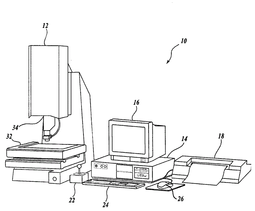
[0022] figure 1 is a block diagram of an exemplary machine vision inspection system 10 that may be used in accordance with the methods described herein. The machine vision inspection system 10 includes a vision measurement machine 12 operatively connected to exc...


PUM


Abstract

A method in a machine vision inspection system for obtaining two images of a workpiece with a desired sub-pixel offset between the images. The images are acquired using a fast multiple image acquisition mode of operation of a camera in the machine vision inspection system. In various implementations, the method includes removing the offset between the images such that the workpiece is congruent in the images and combining the congruent image data. The combined image data has a resolution better than that allowed by the native resolution of a camera that acquires images in the machine vision inspection system. The method may be implemented in an edge feature video tool for measuring edge features on the workpiece. The motion direction utilized for obtaining the two images may be made to be transverse to the edge direction of an edge that is being measured.

Description

technical field [0001] The present invention relates to systems and methods for acquiring images, and more particularly to machine vision inspection systems and methods for acquiring multiple images to be used for measuring operations on workpieces. Background technique [0002] Precision machine vision inspection systems (or simply "vision systems") can be used to obtain precise dimensional measurements of inspected objects, and to inspect a variety of other object characteristics. Such a system may include a computer, camera and optics, and a precision stage movable in multiple directions to allow the camera to scan features of the workpiece being inspected. An exemplary commercially available prior art system is QUICK available from Mitutoyo America Corporation (MAC) located in Aurora IL. PC-based vision system family and software. QUICK is generally described in, for example, the QVPAK 3D CNC Vision Measuring Machine User Guide, published January 2003, and the QVPAK...

Claims


Application Information

Patent Timeline
Patent Type & Authority Applications(China)
IPC IPC(8): G01B11/00G06T7/00
CPCG01N21/8803G01N21/8851G06T3/4069G01B11/02G01B2210/52
Inventor P·G·格拉德尼克
Owner MITUTOYO CORP
Why Eureka
Try Eureka