
Inverter device, or inverter control device for controlling the inverter device

A control device and inverter technology, which is applied to control devices, inverters with reversible, and control drives, etc., can solve the problems of reduced motor efficiency, high switching frequency, low switching frequency, etc., to suppress distortion rate, The effect of improving efficiency

Active Publication Date: 2017-04-12
HITACHI LTD
View PDF4 Cites 0 Cited by
  • Summary
  • Abstract
  • Description
  • Claims
  • Application Information

AI Technical Summary

Problems solved by technology

[0018] Here, losses associated with the on-off operation occur in the switching elements, and since the greater the loss, the higher the cooling performance of the inverter device is required. Therefore, from the point of view of the switching loss of the inverter device, it is expected that the switching frequency Low
[0019] On the other hand, if the switching frequency is lower than the frequency of the fundamental wave of the AC voltage, the distortion of the AC voltage will increase, resulting in a decrease in motor efficiency. Therefore, from the viewpoint of motor efficiency, it is desirable that the switching frequency be high.

Method used


Image

  • Inverter device, or inverter control device for controlling the inverter device
  • Inverter device, or inverter control device for controlling the inverter device
  • Inverter device, or inverter control device for controlling the inverter device

Examples


Embodiment 1

[0071] A first embodiment of the inverter control device for railway vehicles according to the present invention will be described.

[0072] Figure 22 It is a figure which shows an example of the circuit structure of the inverter apparatus in this invention. The railway vehicle smoothes the DC voltage supplied from the trolley line 10 through the current collector with the smoothing reactor 70 and the smoothing capacitor 20, and applies it to the inverter device. The switching circuit of the inverter device consists of a circuit 30a in which a switching element 301 (upper arm) having a diode 305 connected in antiparallel and a switching element 302 (lower arm) having a diode 306 connected in antiparallel are connected in series as a U phase of one phase. , V-phase, and W-phase circuits (30a, 30b, 30c) of three phases. The connection point between the upper arm and the lower arm of each phase serves as an AC output to the AC motor. In addition, the inverter control device 5...


PUM


Abstract

The present invention implements a PWM method that allows for an output of zero voltage to the maximum voltage while keeping a predetermined switching frequency and reduces alternating current ripple even if a condition of a low switching frequency. In a region on a 60-degree basis that is one-sixth of one period of an alternating-current voltage to be output by an inverter device when the one period is 360 degrees, ON-OFF control is performed in switching elements for one phase, and an ON or OFF state is held in switching elements for the other two phases. The phase regions in which the ON-OFF control is performed are phase regions containing the local maximum values or local minimum values of the alternating-current voltages for the respective phases.

Description

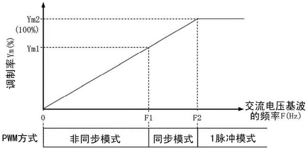
technical field [0001] The present invention relates to an inverter device for converting DC voltage into 3-phase AC voltage. Background technique [0002] In the technical field of railway vehicles, a method of accelerating and decelerating vehicles by operating one to four three-phase AC motors at variable speeds with one inverter device is widely used. The inverter device performs on-off control of a plurality of switching elements based on pulse width modulation (PulseWidth Modulation, PWM), converts a DC voltage into an AC voltage of a desired amplitude and frequency, and applies it to an AC motor. [0003] exist figure 1 The relationship between the amplitude and frequency of an AC voltage fundamental wave generally used in an inverter device for a railway vehicle is shown. The horizontal axis represents the frequency of the AC voltage fundamental wave, and the vertical axis represents the value obtained by normalizing the amplitude of the AC voltage fundamental wave...

Claims


Application Information

Patent Timeline
Patent Type & Authority Patents(China)
IPC IPC(8): H02M7/48H02M7/5387B60L9/22
CPCB60L15/007B60L2200/26B60L2210/40B60L2240/526H02M7/75H02P27/085Y02T10/64Y02T10/72
Inventor 立原周一铃木优人森祐挥
Owner HITACHI LTD
Learn More