
Novel high pitch driving head good in heat dissipation

A drive head, a new type of technology, applied in the field of loudspeakers, can solve the problems of insufficient sealing effect, low voice coil power, and affecting sound quality, and achieve the effects of improving heat dissipation, increasing voice coil power, and improving sound quality

Active Publication Date: 2014-10-15
宁波知音音响设备有限公司
View PDF7 Cites 1 Cited by
  • Summary
  • Abstract
  • Description
  • Claims
  • Application Information

AI Technical Summary

Problems solved by technology

[0002] At present, the common treble driver on the market uses a circular voice coil frame, and the diaphragm directly protrudes from the outside of the voice coil frame, which is easy to break. There will be a gap between the outside and the middle of the drive head, so the sealing effect is not good enough, which will affect the sound quality. Because the back cover of the tweeter drive head is directly matched with the magnetic circuit seal, affected by the material, it will be caused after the treble drive head is used for too long. The heat is relatively large, and the heat dissipation effect cannot be quickly achieved, which will also affect the sound quality, and the circular enameled wire used in the voice coil of this existing tweeter driver head is used as the voice coil, so the power of the voice coil is low and cannot be used. better sound quality

Method used


Image

  • Novel high pitch driving head good in heat dissipation
  • Novel high pitch driving head good in heat dissipation

Examples


Embodiment Construction

[0022] The present invention is described further below with embodiment, is not to limit the scope of implementation of the present invention hereto.

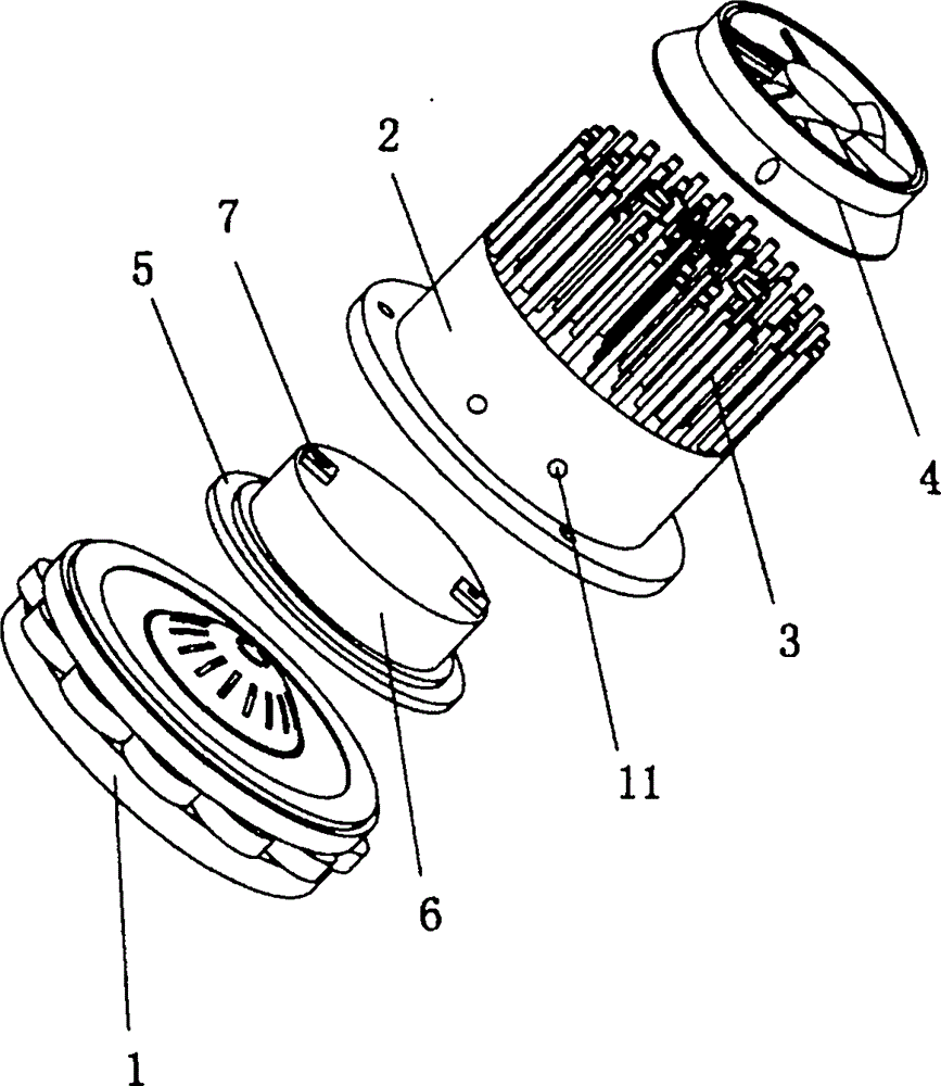
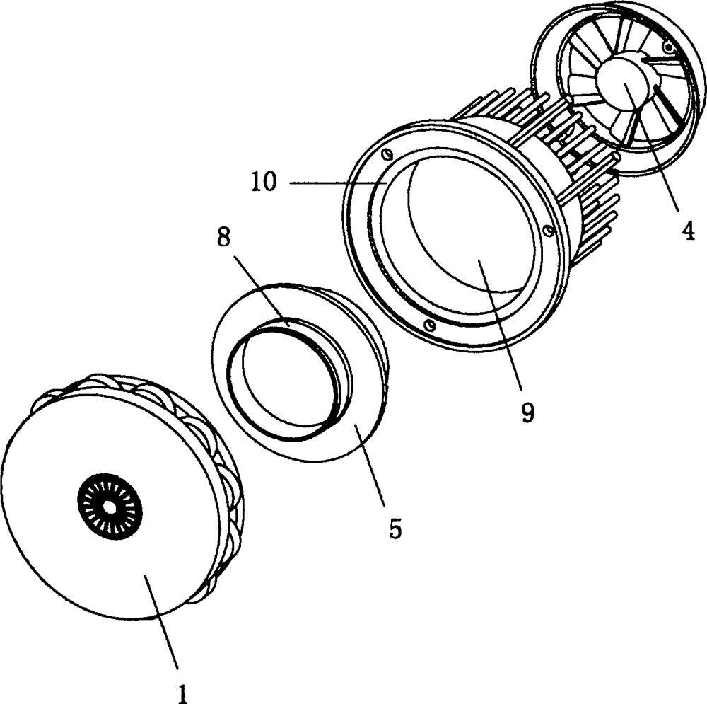
[0023] Such as figure 1 and figure 2 As shown, a new high-pitched driver head with good heat dissipation includes a magnetic circuit 1, a voice coil frame 5, a rear cover 2, and a fan 4. The top of the magnetic circuit 1 is screwed with a rear cover 2, and the top of the rear cover 2 is provided with a There are countless heat dissipation columns 3, the top of the heat dissipation column 3 is screwed with a fan 4, the bottom of the rear cover 2 is provided with a sealed chamber 9, the sealed chamber 9 is provided with a voice coil holder 5, and the bottom of the voice coil holder 5 is Surrounded by a voice coil 8, the top of the voice coil frame 5 is provided with a diaphragm, the top of the voice coil frame 5 is provided with a diaphragm cover 6 sealing the diaphragm, and the top of the diaphragm cover 6 is provided with a w...


PUM


Abstract

The invention relates to the technical field of loudspeakers, in particular to a novel high pitch driving head good in heat dissipation. The novel high pitch driving head good in heat dissipation comprises a magnetic circuit, a rear cover is in screw joint with the top of the magnetic circuit, heat dissipating pillars are arranged on the top of the rear cover, a fan is in screw joint with the tops of the heat dissipating pillars, a sealing chamber is formed in the bottom of the rear cover, a voice coil rack is arranged in the sealing chamber, a voice coil is arranged on the periphery of the bottom of the voice coil rack in a surrounding mode, a vibrating diaphragm is arranged on the top of the voice coil rack, a vibrating diaphragm cover is arranged on the top of the voice coil rack, binding posts are arranged on the top of the vibrating diaphragm cover, a sealing groove concentric with the sealing chamber is formed in the bottom of the rear cover, and wiring holes are formed in the side face of the rear cover. According to the novel high pitch driving head good in heat dissipation, a flat tin voice coil is adopted, the rear cover and the heat dissipating pillars are made of aluminum alloy materials, the fan is arranged on the top of the heat dissipating pillars, and thus the power of the high pitch voice coil is improved, the voice quality is improved, and the head dissipating effect is improved. In addition, the voice coil rack is sealed in the sealing chamber of the rear cover, the excellent sealing effect can be achieved, and broken voices or influences on the voice quality can be avoided.

Description

technical field [0001] The invention relates to the technical field of loudspeakers, in particular to a novel high-pitched driving head with good heat dissipation. Background technique [0002] At present, the common treble driver on the market uses a circular voice coil frame, and the diaphragm directly protrudes from the outside of the voice coil frame, which is easy to break. There will be a gap between the outside and the middle of the drive head, so the sealing effect is not good enough, which will affect the sound quality. Because the back cover of the tweeter drive head is directly matched with the magnetic circuit seal, affected by the material, it will be caused after the treble drive head is used for too long. The heat is relatively large, and the heat dissipation effect cannot be quickly achieved, which will also affect the sound quality, and the circular enameled wire used in the voice coil of this existing tweeter driver head is used as the voice coil, so the po...

Claims


Application Information

Patent Timeline
Patent Type & Authority Applications(China)
IPC IPC(8): H04R9/02H04R9/06
Inventor 沈奇炳
Owner 宁波知音音响设备有限公司
Features
  • Generate Ideas
  • Intellectual Property
  • Life Sciences
  • Materials
  • Tech Scout
  • Unparalleled Data Quality
  • Higher Quality Content
  • 60% Fewer Hallucinations
Learn More