Buoyancy-tank type upstream control weir gate

A floating box type, floating box technology, applied in the field of floating box type upstream control weir gate, can solve the problems of energy waste, easy failure, high cost, etc., and achieve the effect of ensuring sealing, simple control, and simple structure

Inactive Publication Date: 2014-10-22
WUHAN SHENGYU DRAINING SYST
View PDF4 Cites 28 Cited by
  • Summary
  • Abstract
  • Description
  • Claims
  • Application Information

AI Technical Summary

Problems solved by technology

Generally, the start of the weir gate often requires power from the power equipment. Because this kind of weir gate requires additional motors, water level sensors, driving and transmission devices, etc., the structure is relatively complicated, prone to failure, and it is very inconvenient to install and disassemble.
This kind of weir gate is not easy to repair and maintain, the cost is high, and because of the uninterrupted power supply, it also causes a waste of energy

Method used


Image

  • Buoyancy-tank type upstream control weir gate
  • Buoyancy-tank type upstream control weir gate
  • Buoyancy-tank type upstream control weir gate

Examples


Embodiment Construction

[0021] The present invention will be further described below in conjunction with accompanying drawing.

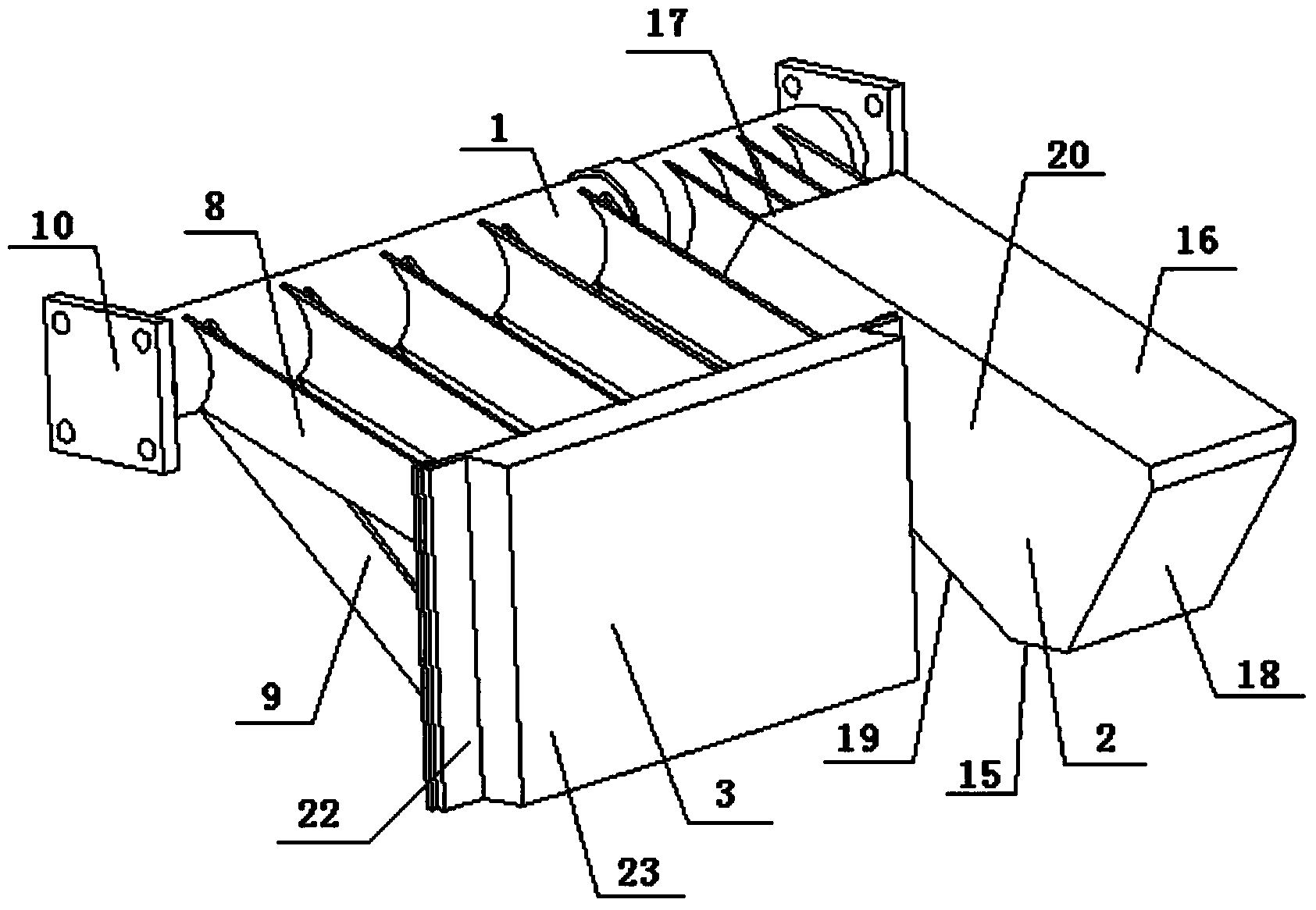
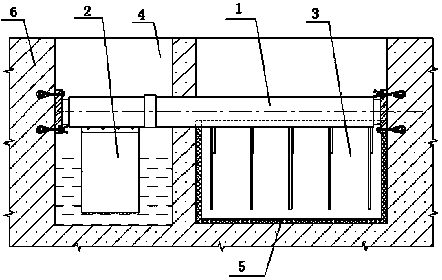
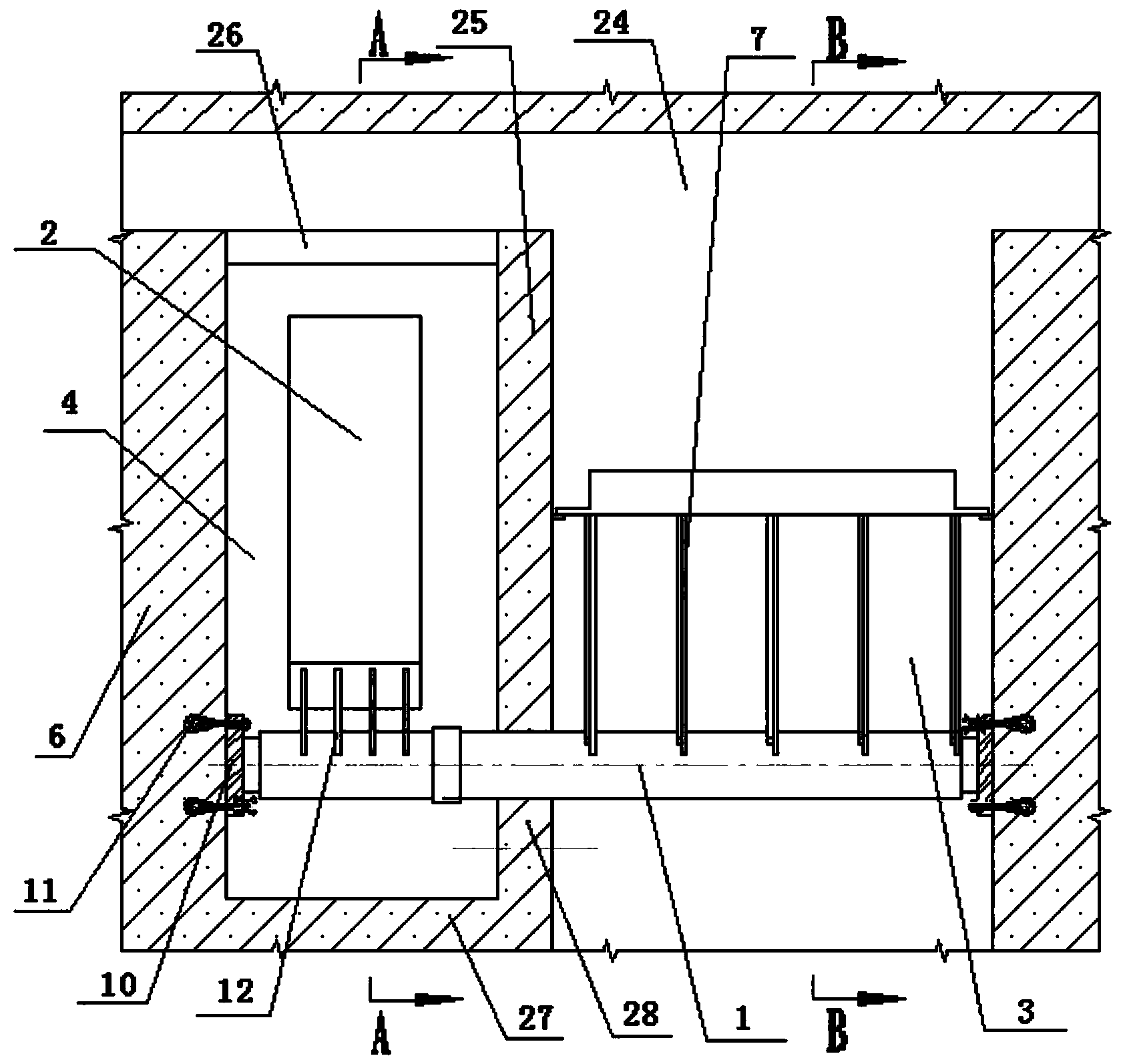
[0022] Such as image 3 As shown, the weir gate among the present invention comprises waterway 24, waterway side wall 6, weir gate plate 3, buoyancy tank 2, rotating shaft 1 and buoyancy tank chamber 4, and buoyancy tank chamber 4 is arranged in the waterway, is formed by the waterway side wall 6 The rectangular cavity surrounded by the pontoon chamber side walls 25 connected with the waterway side walls 6 on three sides, wherein the pontoon chamber side walls 25 include the front side wall 26 of the pontoon chamber, the rear side wall 27 of the pontoon chamber and the right side of the pontoon chamber. side wall 28 . A gap is provided at the top of the front side wall 26 of the floating tank chamber upstream of the rotating shaft 1, which is the water inlet 13 of the floating tank chamber, and a small gap is formed at the bottom of the right side wall 28 of the floating t...


PUM


Abstract

The invention relates to the technical field of water draining, in particular to a buoyancy-tank type upstream control weir gate. The buoyancy-tank type upstream control weir gate comprises a rotating shaft, a buoyancy tank and a weir gate plate, wherein the rotating shaft, the buoyancy tank and the weir gate plate are arranged in a water channel. The buoyancy tank is arranged at one end of the rotating shaft through buoyancy-tank supporting arms, the weir gate plate is fixed to the rotating shaft through weir gate plate supporting arms, and the buoyancy tank and the weir gate plate are located on the same side of the rotating shaft. According to the buoyancy-tank type upstream control weir gate, the mode that the rotating shaft rotates to control the weir gate to be opened is adopted, the buoyancy tank is pushed by buoyancy force to rotate, a weir gate body on the same side is accordingly driven to be opened, additional energy input is not needed, a water level inductor is also not needed, the buoyancy-tank type upstream control weir gate is simple in structure and low in cost, and energy is saved.

Description

technical field [0001] The invention relates to the technical field of drainage, in particular to a floating box type upstream control weir gate. Background technique [0002] The upstream control weir gate is set between the upstream rainwater pipeline and the rainwater storage tank, or between the sewage pipe network and the sewage treatment plant, and is used to control the upstream rainwater pipeline to discharge flood to the rainwater storage tank during heavy rain. Generally, the start of the weir gate often requires power equipment to apply power. Because this kind of weir gate requires additional motors, water level sensors, driving and transmission devices, etc., the structure is relatively complicated, prone to failure, and installation and disassembly are very inconvenient. This kind of weir gate is inconvenient to repair and maintain, the cost is high, and because of the uninterrupted power supply, it also causes waste of energy. Contents of the invention [0...

Claims


Application Information

Patent Timeline
Patent Type & Authority Applications(China)
IPC IPC(8): E02B7/50
Inventor 周超
Owner WUHAN SHENGYU DRAINING SYST
Why Eureka
Try Eureka