Method and device for plugging leaking point of flange face and sealing gasket of high-pressure equipment

A technology for sealing gaskets and high-pressure equipment, which is applied in flange connections, mechanical equipment, pipes/pipe joints/fittings, etc., and can solve the problems of inability to meet the normal production requirements of iron and steel making, difficult to maintain, and long maintenance cycles. , to achieve the effect of simple and easy implementation, low cost of manufacturing equipment, and improved production capacity and efficiency

Inactive Publication Date: 2014-10-22
BAOSHAN IRON & STEEL CO LTD
View PDF8 Cites 4 Cited by
  • Summary
  • Abstract
  • Description
  • Claims
  • Application Information

AI Technical Summary

Problems solved by technology

At this time, only asbestos strips are embedded on the flange surface of the leakage point and pressure injection is performed. Asbestos strips and glue injection will be in a state of high temperature and high pressure for a long time, it is difficult for them to maintain a long fixed repair cycle, so it cannot meet the normal production needs of iron and steel making

Method used


Image

  • Method and device for plugging leaking point of flange face and sealing gasket of high-pressure equipment
  • Method and device for plugging leaking point of flange face and sealing gasket of high-pressure equipment
  • Method and device for plugging leaking point of flange face and sealing gasket of high-pressure equipment

Examples


Embodiment Construction

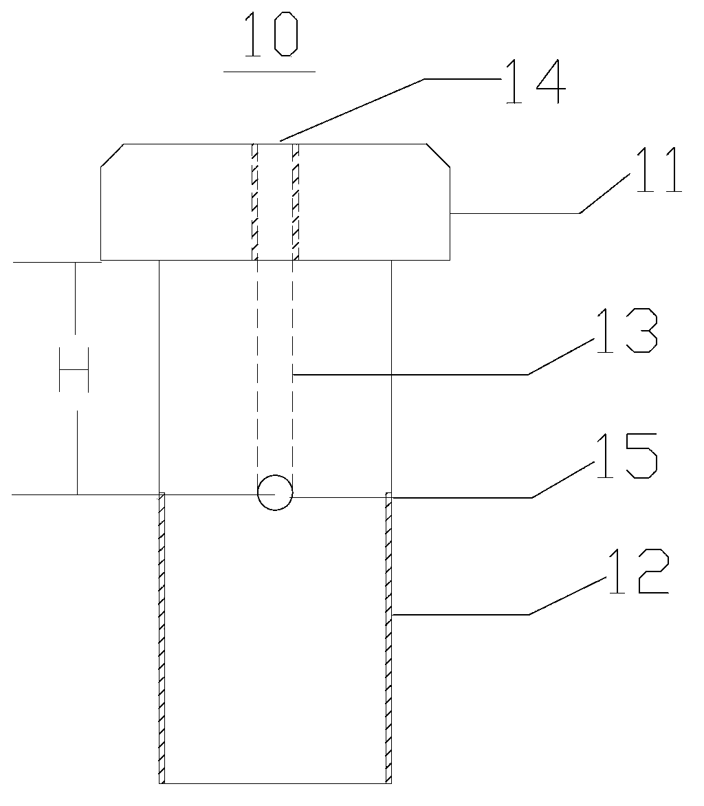
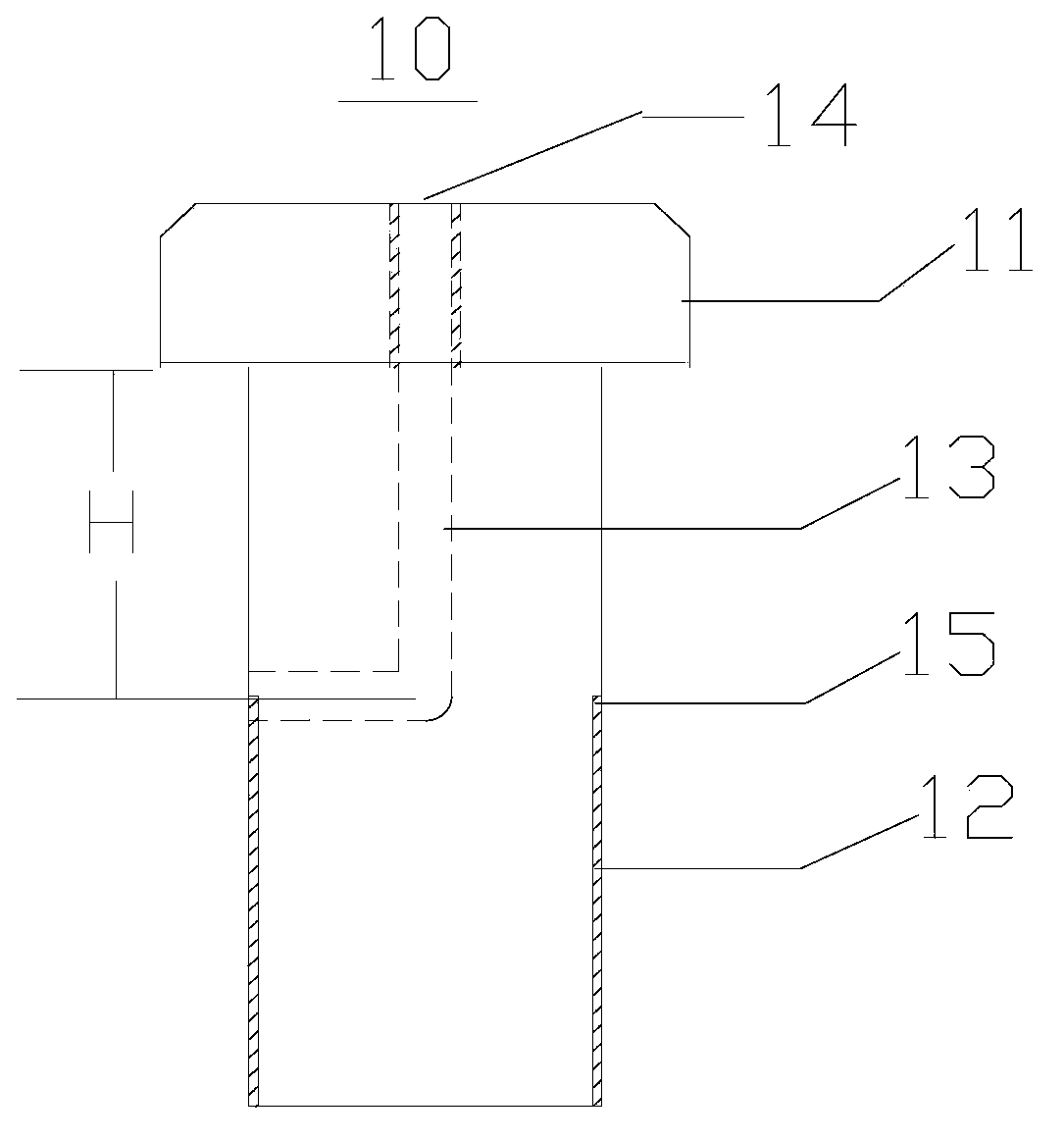
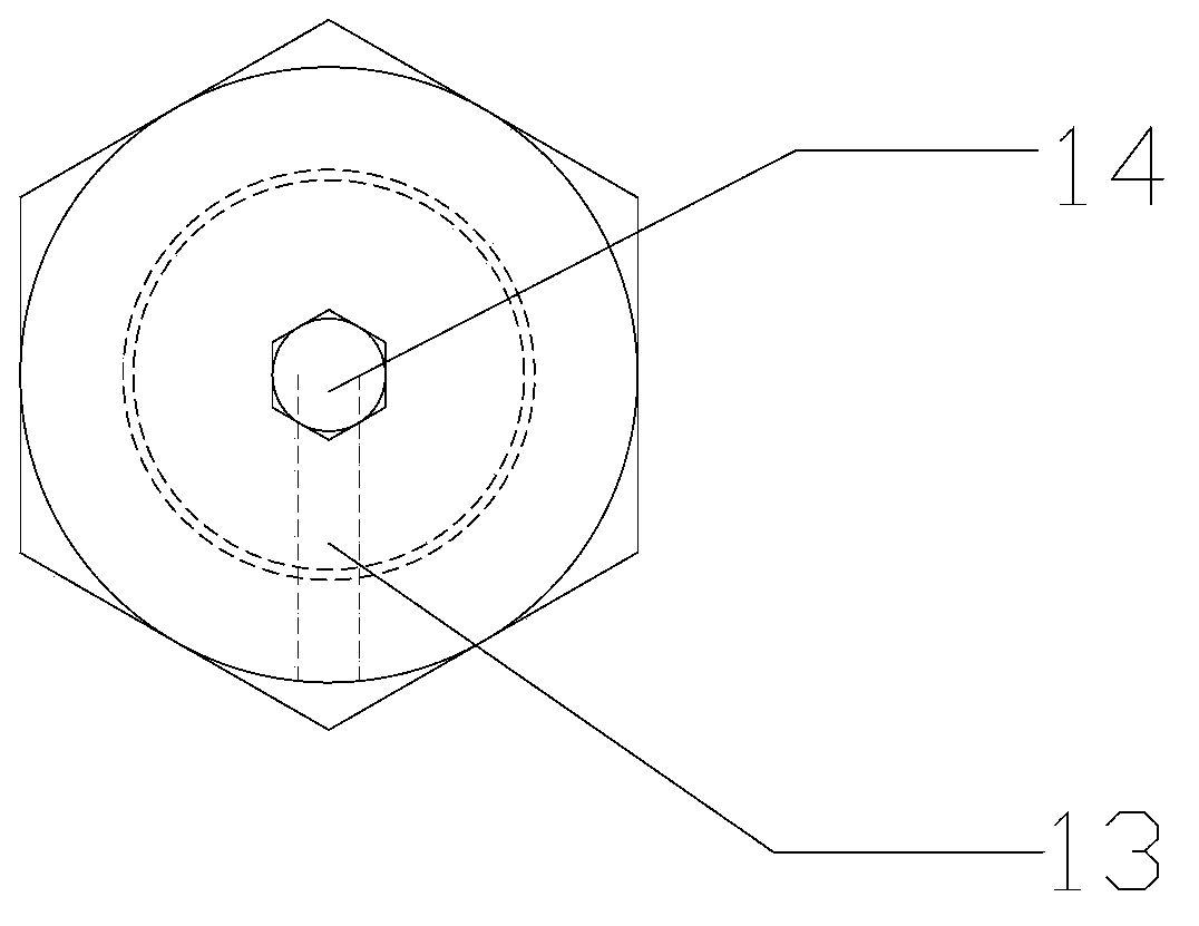
[0028] The method and device for sealing the leakage of the flange surface of the high-pressure equipment and the sealing gasket according to the present invention will be further described according to the specific embodiments and the accompanying drawings, but the specific embodiments and related descriptions do not constitute a reference to the present invention. Improper limitation of technical solutions.

[0029] Follow the steps below to seal the flange surface of the high-pressure equipment and the leakage point of the sealing gasket:

[0030] (1) Judging the location of the leakage point according to the on-site sound and ash emission;

[0031] (2) On the outside of the flange surface of the leakage point, weld the angle iron or flat iron to the flange, so that a sealed space is formed between the angle iron or flat iron, the flange surface and the bolts to prevent leakage in the subsequent steps. The sealant is squeezed and leaked, wherein the length of the angle iro...


PUM


Abstract

The invention discloses a method for plugging a leaking point of a flange face and a sealing gasket of high-pressure equipment. The method includes the following steps: disposing a glue injection bolt in a bolt hole, and enabling an outlet of an L-shaped hole to be positioned at the leaking point of the flange face and the sealing gasket, wherein the glue injection bolt is provided with the L-shaped hole formed downwards from the head of the glue injection bolt along the axial direction, and the L-shaped hole is a glue injection passage; injecting a sealing agent through the glue injection passage to plug the leaking point; screwing a sealing bolt into the L-shaped hole to seal the glue injection bolt, wherein the sealing bolt is matched with the L-shaped hole. Correspondingly, the invention further discloses a device used in the method. The device comprises the glue injection bolt and the sealing bolt. The glue injection bolt is provided with the L-shaped hole downwards formed from the head of the glue injection bolt along the axial direction, an outlet end of the L-shaped hole is communicated with the outside, and outer diameter of the sealing bolt is matched with inner diameter of the L-shaped hole. The method and the device have the advantages that the leaking point, positioned on the flange face and the sealing gasket, of the high-pressure equipment can be plugged quickly, conveniently and effectively.

Description

technical field [0001] The invention relates to a plugging method and a device thereof, in particular to a plugging method and a device for high-voltage equipment. Background technique [0002] In the process of ironmaking and steelmaking production, more high-pressure and high-temperature reaction equipment will be involved. Take the blast furnace used for ironmaking as an example. Under normal production conditions, the actual top pressure of the blast furnace is 220-270Kpa, the top temperature is 120°C-300°C, and the top contains a lot of dusty raw gas. At the same time, the air supply system The pressure reached 400 ~ 450Kpa, while the temperature reached 1250 ℃. Since the blast furnace is always under high temperature and high pressure and contains a large amount of raw gas during the production process, high requirements are put forward for the working conditions of the blast furnace, especially the sealing performance. If the high-voltage equipment such as blast fur...

Claims


Application Information

Patent Timeline
Patent Type & Authority Applications(China)
IPC IPC(8): F16L23/16
CPCF16L23/165
Inventor 乐鸣王训富李有庆潘景照
Owner BAOSHAN IRON & STEEL CO LTD
Why Eureka
Try Eureka