Pressure barrel and water purifier with same

A technology for pressure barrels and sealing parts, applied in pressure vessels, mechanical equipment, water/sewage treatment, etc., can solve problems such as pressure barrel leakage, water storage layer, pressure-holding layer seal failure, water purifier failure, etc., to achieve reliable The effect of sealing and eliminating air leakage points

Active Publication Date: 2015-07-29
GREE ELECTRIC APPLIANCES INC
View PDF6 Cites 0 Cited by
  • Summary
  • Abstract
  • Description
  • Claims
  • Application Information

AI Technical Summary

Problems solved by technology

When the steel ring has deformation, poor welding defects, coordination displacement between the three layers, and surface defects, the gaps between the layers will not be completely sealed, which will eventually lead to the failure of the water storage layer and the pressure-preserving layer. The seal fails, which in turn causes internal water leakage in the pressure tank, causing the water purifier to fail due to insufficient water pressure inside the pressure tank, affecting the normal use of the user

Method used


Image

  • Pressure barrel and water purifier with same
  • Pressure barrel and water purifier with same
  • Pressure barrel and water purifier with same

Examples


Embodiment Construction

[0029] The present invention will be described in detail below with reference to the accompanying drawings and examples. It should be noted that, in the case of no conflict, the following embodiments and features in the embodiments can be combined with each other.

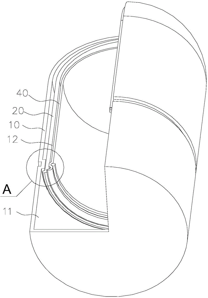
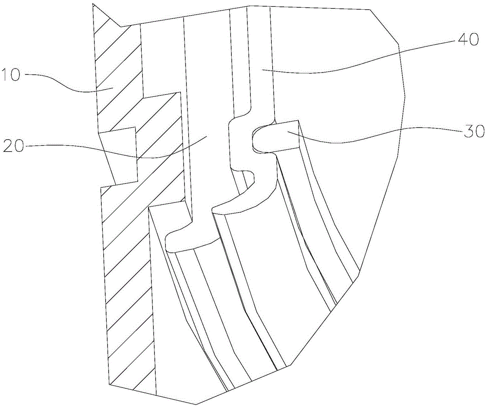
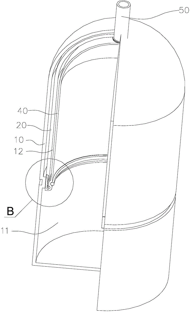
[0030] In one embodiment of the present invention, a pressure barrel is provided, such as image 3 and Figure 4 As shown, the pressure barrel includes a cylinder body 10, a compression ring 30 and a diaphragm 40, wherein the cylinder body 10 has an inner cavity, and an annular boss 13 protruding into the inner cavity is provided on the peripheral wall of the inner cavity. The diaphragm 40 has a peripheral first seal 41 . The compression ring 30 is pressed against the first sealing part 41 of the diaphragm 40, so that the first sealing part 41 is sealed with the annular boss 13, and the gap between the diaphragm 40 and the lower inner wall of the cylinder body 10 is A pressure-holding chamber 12 is formed betwee...


PUM


Abstract

The invention discloses a pressure barrel and a water purifier with the same. The pressure barrel comprises a barrel, a diaphragm and a press ring, wherein the barrel is provided with an inner cavity, the peripheral wall of the inner cavity is provided with annular bosses raised to the inner part of the inner cavity, the diaphragm is provided with a first sealing part located all around the pressure barrel and the press ring is pressed on the first sealing part of the diaphragm so that the first sealing part is hermetically matched with the boss; the surface of the first sealing part which is in contact with the boss is provided with an annular first bulge matched with the surface of the boss so as to form a linear sealing structure. According to the pressure barrel and the water purifier with the same provided by the invention, the surface of the first sealing part of the pressure barrel diaphragm which is in contact with the bulge is provided with the annular first bulge matched with the surface of the boss to form the linear sealing structure, and air leakage points between the diaphragm and the barrel can be eliminated, therefore the reliable sealing between a water storage cavity and a pressure maintaining cavity can be realized.

Description

technical field [0001] The invention relates to the field of water treatment, in particular to a pressure tank and a water purifier with the pressure tank. Background technique [0002] The pressure tank is a key component of the water purifier system. Its function is to store the water that has been treated by the purification system, and reserve enough clean water with sufficient water pressure for the user, so that the user can turn on the switch at any time to drink clean water and ensure clean water. The comfort and convenience of using the whole water machine. [0003] Such as figure 1 As shown, the internal structure of the existing pressure tank is composed of three layers of rubber diaphragm 40, PP lining 20 and cylinder body 10 from inside to outside, wherein, rubber diaphragm 40-PP lining 20 is a water storage layer, and rubber diaphragm 40-PP lining 20 is a water storage layer, and the rubber diaphragm 40—The inner wall of the bottom of the cylinder body 10 is ...

Claims


Application Information

Patent Timeline
Patent Type & Authority Applications(China)
IPC IPC(8): F16J12/00C02F1/00
CPCC02F1/00F16J12/00
Inventor 黄辉方祥建颜小林郑为光
Owner GREE ELECTRIC APPLIANCES INC
Why Eureka
Try Eureka