Antenna alignment method, antenna alignment device and antenna alignment system

An antenna and angle pair technology, applied in the field of communication, can solve the problems of low antenna alignment efficiency and so on

Active Publication Date: 2014-10-22
HUAWEI TECH CO LTD
View PDF6 Cites 20 Cited by
  • Summary
  • Abstract
  • Description
  • Claims
  • Application Information

AI Technical Summary

Problems solved by technology

[0005] Embodiments of the present invention provide an antenna alignment method...

Method used


Image

  • Antenna alignment method, antenna alignment device and antenna alignment system
  • Antenna alignment method, antenna alignment device and antenna alignment system
  • Antenna alignment method, antenna alignment device and antenna alignment system

Examples


Embodiment 1

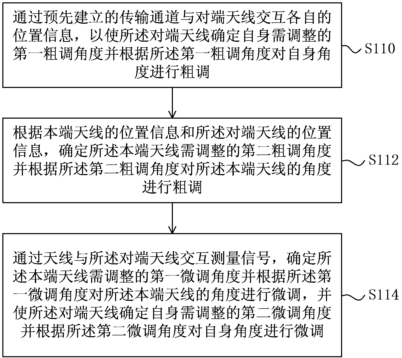
[0105] figure 1 This is a flowchart of the antenna alignment method provided by Embodiment 1 of the present invention. The method of this embodiment is applicable to the situation where the microwave wireless communication antenna needs to be aligned. The method is performed by an antenna alignment device, which is usually implemented in hardware and / or software and integrated in a microwave wireless communication antenna (hereinafter referred to as an antenna). The method of this embodiment includes the following steps:

[0106] Step 110: Exchange respective position information with the opposite-end antenna through the pre-established transmission channel, so that the opposite-end antenna determines the first coarse adjustment angle to be adjusted by itself and performs a coarse adjustment on its own angle according to the first coarse adjustment angle. tune.

[0107] For the convenience of description, the antenna integrated with the antenna alignment device as the execu...

Embodiment 2

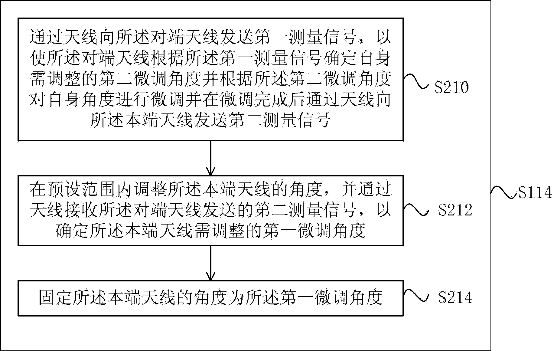
[0145] The second embodiment further refines step 114 on the basis of the antenna alignment method provided in the first embodiment of the present invention. figure 2 It is a schematic flowchart of step 114 in the antenna alignment method provided by Embodiment 2 of the present invention. like figure 2 As shown, step 114 includes:

[0146] Step 210: Send a first measurement signal to the opposite-end antenna through the antenna, so that the opposite-end antenna determines a second fine-tuning angle that needs to be adjusted according to the first measurement signal and adjusts itself according to the second fine-tuning angle. The angle is fine-tuned, and after the fine-tuning is completed, a second measurement signal is sent to the local antenna through the antenna.

[0147] Specifically, the opposite-end antenna determines a second fine-tuning angle that needs to be adjusted according to the received signal strength of the first measurement signal sent by the local-end an...

Embodiment 3

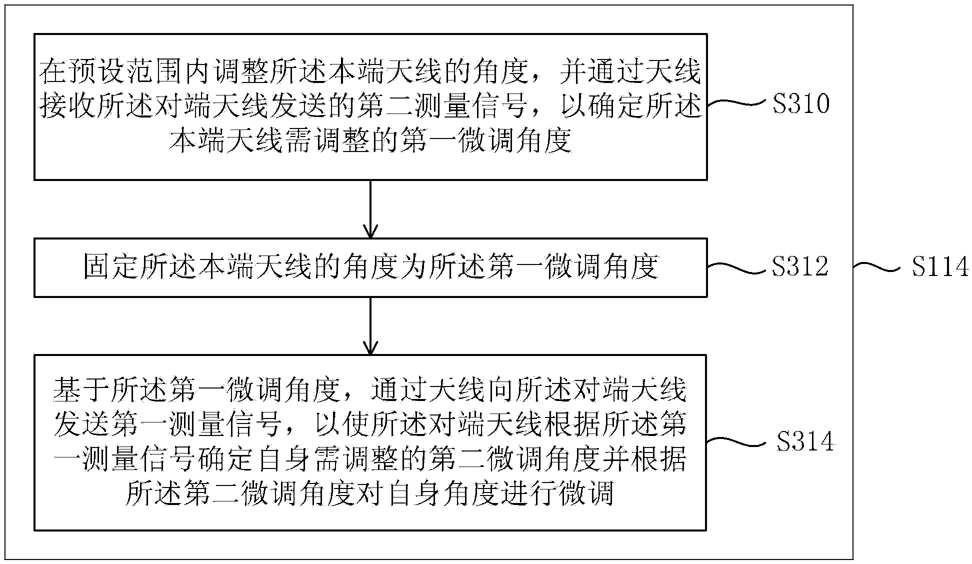
[0169] The third embodiment further refines step 114 on the basis of the antenna alignment method provided in the first embodiment of the present invention. image 3 This is a schematic flowchart of step 114 in the antenna alignment method provided by Embodiment 3 of the present invention. like image 3 As shown, step 114 includes:

[0170] Step 310: Adjust the angle of the local antenna within a preset range, and receive the second measurement signal sent by the opposite antenna through the antenna to determine a first fine-tuning angle to be adjusted by the local antenna.

[0171]Step 312: Fix the angle of the local antenna to be the first fine-tuning angle.

[0172] For the specific implementation of step 310 and step 312, refer to step 212 and step 214 in the second embodiment.

[0173] Step 314: Based on the first fine-tuning angle, send a first measurement signal to the opposite-end antenna through the antenna, so that the opposite-end antenna determines the second fi...


PUM


Abstract

The embodiment of the invention provides an antenna alignment method, an antenna alignment device and an antenna alignment system. The embodiment of the invention provides an antenna alignment method comprising the following steps: position information interaction with an opposite-end antenna is performed through a pre-established transmission channel to enable the opposite-end antenna to determine a first coarse adjustment angle at which the opposite-end antenna needs to be adjusted and to coarsely adjust the angle according to the first coarse adjustment angle; a second coarse adjustment angle at which a local-end antenna needs to be adjusted is determined according to the position information of the local-end antenna and the position information of the opposite-end antenna, and the angle of the local-end antenna is coarsely adjusted according to the second coarse adjustment angle; and a first fine adjustment angle at which the local-end antenna needs to be adjusted is determined through measurement signal interaction between the local-end antenna and the opposite-end antenna, the angle of the local-end antenna is finely adjusted, and the opposite-end antenna determines a second fine adjustment angle at which the opposite-end antenna needs to be adjusted, and finely adjusts the angle according to the second fine adjustment angle. According to the embodiment of the invention, the efficiency of antenna alignment is improved.

Description

technical field [0001] Embodiments of the present invention relate to technologies in the field of communications, and in particular, to an antenna alignment method, device, and system. Background technique [0002] In point-to-point microwave wireless backhaul communication, after selecting the sites of both communication parties, it is necessary to align the antennas of both communication parties so that both parties can obtain better quality signals. Microwave communications in my country are widely used in L-band (radio waves with a frequency of 1-2GHz and a wavelength of 300.00-150.00mm), S-band (radio waves with a frequency of 2-4GHz and a wavelength of 150.00-75.00mm), and C-band (with a frequency of 4- 8GHz, radio waves with a wavelength of 75.00-37.50mm), X-band (radio waves with a frequency of 8-12GHz and a wavelength of 37.5.00-25mm), K-band (radio waves with a frequency of 18-27GHz and a wavelength of 16.67.00-11.11mm) wave) applications are still under developmen...

Claims


Application Information

Patent Timeline
IPC IPC(8): H04B7/02H04B17/00G05D3/12
Inventor 阳建军陈卫民夏林峰刘云
Owner HUAWEI TECH CO LTD
Why Eureka
Try Eureka