

Threaded joint for pipes
A technology for threaded joints and pipes, which is applied in the direction of threaded connections, pipes/pipe joints/fittings, drill pipes, etc., can solve the problems of airtightness deterioration of threaded joints, improve wear resistance and rust resistance, and prevent pressure The effect of overgrowth
Active Publication Date: 2014-10-22
NIPPON STEEL CORP +1
View PDF7 Cites 12 Cited by
- Summary
- Abstract
- Description
- Claims
- Application Information
AI Technical Summary
Problems solved by technology
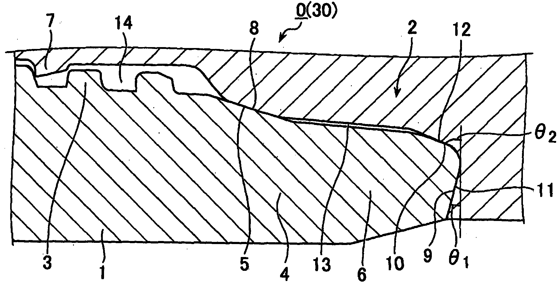
If the pressure of the fluid confined in the non-contact area 13 becomes high due to an increase in the amount of fluid, the non-contact area 13 tends to expand radially due to the pressure and is achieved by the tight contact between the pin and the sealing surface of the box There is a possibility of deterioration of the airtightness of the threaded joint
Method used
View moreImage
Smart ImageViewing Examples

Examples
Embodiment
[0134] A threaded joint for pipes having the dimensions shown in Table 1 was used to perform a sealing test (a test in which internal and external pressures are applied to the threaded joint while a tensile load and a compressive load are applied to the threaded joint). The threaded joint has Figure 1A to Figure 1C as well as Figure 2A with Figure 2B In the shape shown in, the groove 9a formed on the shoulder surface has the width and depth shown in Table 1.
Login to View More PUM
 Abstract
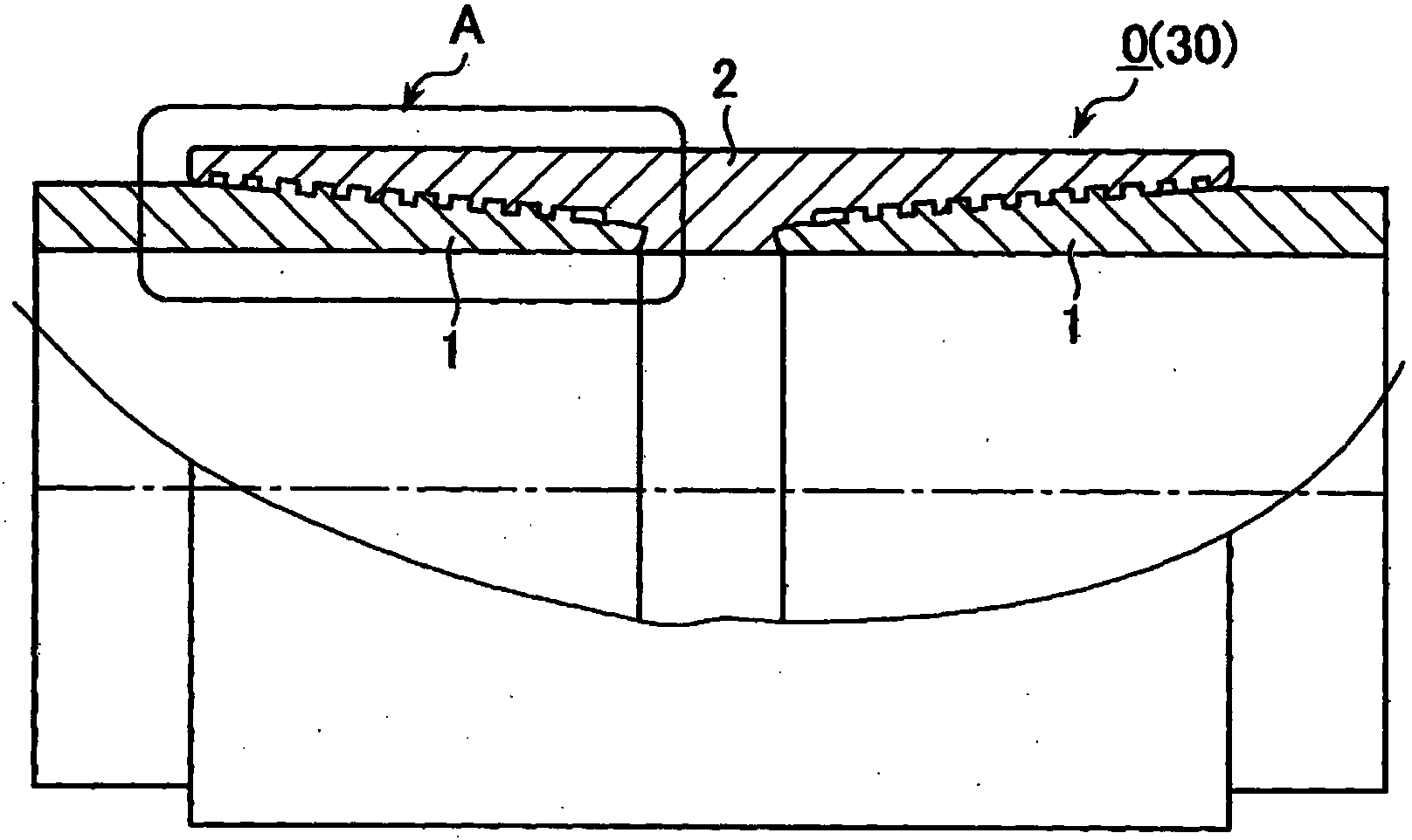
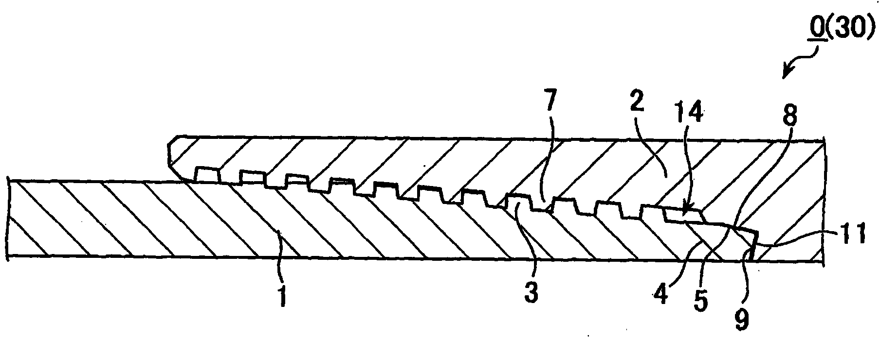
A threaded joint for pipes comprises a pin 1 and a box 2 each having a contact surface including a threaded portion 3,7 and an unthreaded metal contact portion. The unthreaded metal contact portion includes a sealing surface 5, 8 and a shoulder surface 9, 10, 11, 12. The shoulder surface of the pin is located on the end surface of the pin. A non-contacting region 13 in which the pin and the box do not contact each other is present between the sealing surfaces and the shoulder surfaces of the pin and the box. The threaded joint has one or more grooves formed in the shoulder surface of at least one of the pin and the box and extending to the non-contacting region and to the interior of the threaded joint. At least the contact surface of at least one of the pin and the box has a solid lubricating coating exhibiting plastic or viscoplastic rheological behavior formed thereon. The total volume V (mm3) of the grooves and the coating weight W (g) of the solid lubricating coating satisfy the equation V / W >= 24 (mm3 / g).
Description
Technical field [0001] The present invention relates to a threaded joint for pipes (also called tubular threaded joints), which is suitable for connecting pipes for the petroleum industry and has grooves on the shoulder surface thereof to allow high pressure fluid to leak out. Specifically, the present invention relates to a threaded joint for pipes that prevents deterioration of the performance of a groove by a solid lubricant coating. Background technique [0002] In recent years, oil wells have become deeper and developed in increasingly harsh environments. For this reason, it is strongly desired that tubular threaded joints for connecting pipes for the petroleum industry including tubing and casing for oil wells or gas wells have enhanced compression resistance and improvement under internal and external pressures. The sealing characteristics. [0003] Figure 1A Is a cross-sectional view schematically showing the structure of a typical pipe threaded joint, Figure 1B Yes Figu...
Claims
Login to View More Application Information
Patent Timeline
 Patent Type & AuthorityApplications(China)
IPC IPC(8): F16L15/04
CPCC10M2207/026E21B17/08C10N2210/05C10M171/00C10M2201/062C10M2207/1253C10M2205/0225C10M2205/022F16L58/182C10M2229/041F16L15/004C10M2205/183C10M2201/042C10M2209/084C10M2205/18C10N2010/04E21B17/042C10N2010/10C10N2010/08
Inventor大岛真宏鹈饲信冈田隆志佐佐木优嘉山口优杉野正明
OwnerNIPPON STEEL CORP