Efficient dyeing machine

A kind of dyeing machine, high-efficiency technology, applied in the field of dyeing machines, can solve the problems of unfavorable mechanical mass production, waste of time, waste of manpower, etc., and achieve the effects of improving dyeing speed and dyeing quality, dyeing uniformity, and saving energy

Active Publication Date: 2014-10-29
徐州国宏包装有限公司
View PDF6 Cites 7 Cited by
  • Summary
  • Abstract
  • Description
  • Claims
  • Application Information

AI Technical Summary

Problems solved by technology

[0003] On the other hand, the dyeing machines are all single units. After dyeing, the power of the device needs to be cut off before th

Method used


Image

  • Efficient dyeing machine
  • Efficient dyeing machine

Examples


Embodiment Construction

[0013] The following will clearly and completely describe the technical solutions in the embodiments of the present invention with reference to the accompanying drawings in the embodiments of the present invention. Obviously, the described embodiments are only some, not all, embodiments of the present invention. Based on the embodiments of the present invention, all other embodiments obtained by persons of ordinary skill in the art without making creative efforts belong to the protection scope of the present invention.

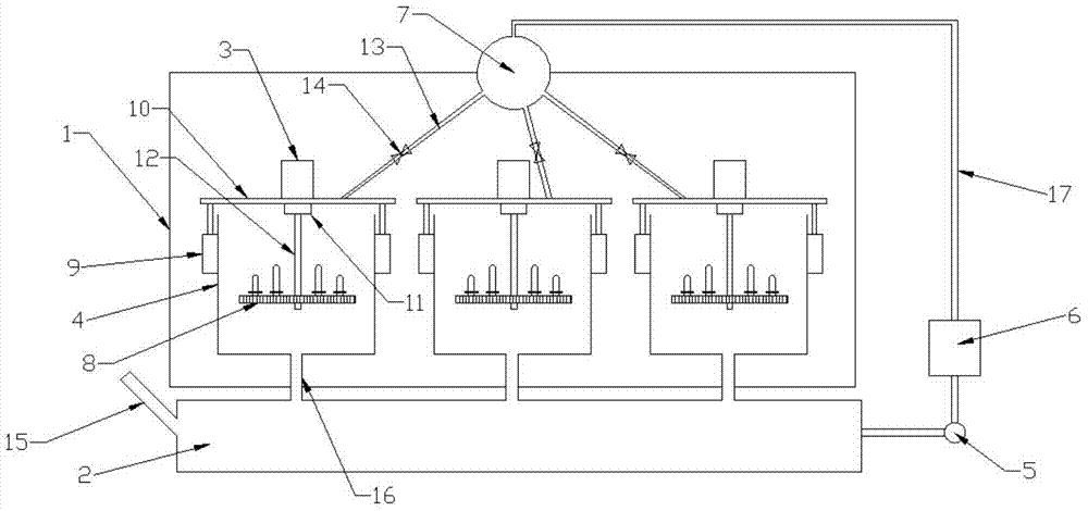
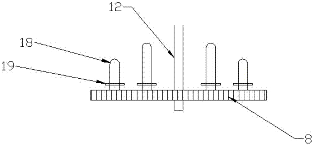
[0014] see Figure 1-2 , in an embodiment of the present invention, a high-efficiency dyeing machine includes a support frame 1, a motor 3, a body 4, a water pump 5, a movable cover 10, a hose 13 and a water pipe 17; Body 4; two telescopic sleeves 9 on the same horizontal plane are installed on the outer wall of the body 4; The lower surface of the motor 3 is installed on the movable cover 10; the output shaft of the motor 3 extends into the body 4, and the o...


PUM


Abstract

The invention discloses an efficient dyeing machine which comprises a supporting frame, a motor, machine bodies, a water suction pump, a movable cover, a hose and a water pipe. Three sets of the machine bodies of identical structures are fixed in the supporting frame. Two telescopic sleeves on the same horizontal plane are mounted on the outer wall of each machine body. The telescopic sleeves are mounted vertically, and movable rods of the telescopic sleeves are fixedly connected to the lower surface of the movable cover in an upward mode. The motor is mounted on the upper face of the movable cover. An output shaft of the motor stretches into the machine bodies, and a reducer is connected to the output shaft of the motor. Cloth rotates on a hanging tray and makes full contact with liquid for dyeing, and dyeing is uniform; multiple sets of machine bodies are arranged, a great amount of cloth can be dyed, energy can be saved, and a power supply does not need to be started or shut down frequently; the cloth is convenient to load and unload, airtightness of the inner portions of the machine bodies is guaranteed at the same time, and the efficient dyeing machine improves the dyeing speed and dyeing quality of products.

Description

technical field [0001] The invention relates to a dyeing machine, in particular to a high-efficiency dyeing machine. Background technique [0002] At present, the generally used dyeing machine is a jet dyeing machine. This dyeing machine is to hang the cloth cover on the rotating nozzle and rotate with the nozzle driven by the transmission mechanism. When dyeing, the dyeing liquid is sprayed onto the cloth through the dyeing liquid supply device arranged on the machine body through the nozzle with nozzle holes, so as to achieve the purpose of dyeing. [0003] On the other hand, the dyeing machines are all single units. After dyeing, the power of the device needs to be cut off to take out the cloth. This operation is a waste of time and manpower, which is not conducive to mass production of the machine. Contents of the invention [0004] The object of the present invention is to provide a high-efficiency dyeing machine with uniform dyeing, multiple sets of bodies, and ener...

Claims


Application Information

Patent Timeline
IPC IPC(8): D06B1/02D06B23/00
Inventor 费志瑾
Owner 徐州国宏包装有限公司
Why Eureka
Try Eureka