System and method for gas purge control

一种节气门、进气歧管的技术,应用在电气控制、装料系统、发动机控制等方向,能够解决不新鲜空气系统等问题

Active Publication Date: 2014-10-29
FORD GLOBAL TECH LLC
View PDF6 Cites 21 Cited by
  • Summary
  • Abstract
  • Description
  • Claims
  • Application Information

AI Technical Summary

Problems solved by technology

In particular, when the intake throttle is opened to a greater extent, the manifold vacuum can decrease, thus creating a stale air system in the crankcase ventilation system

Method used


Image

  • System and method for gas purge control
  • System and method for gas purge control
  • System and method for gas purge control

Examples


Embodiment Construction

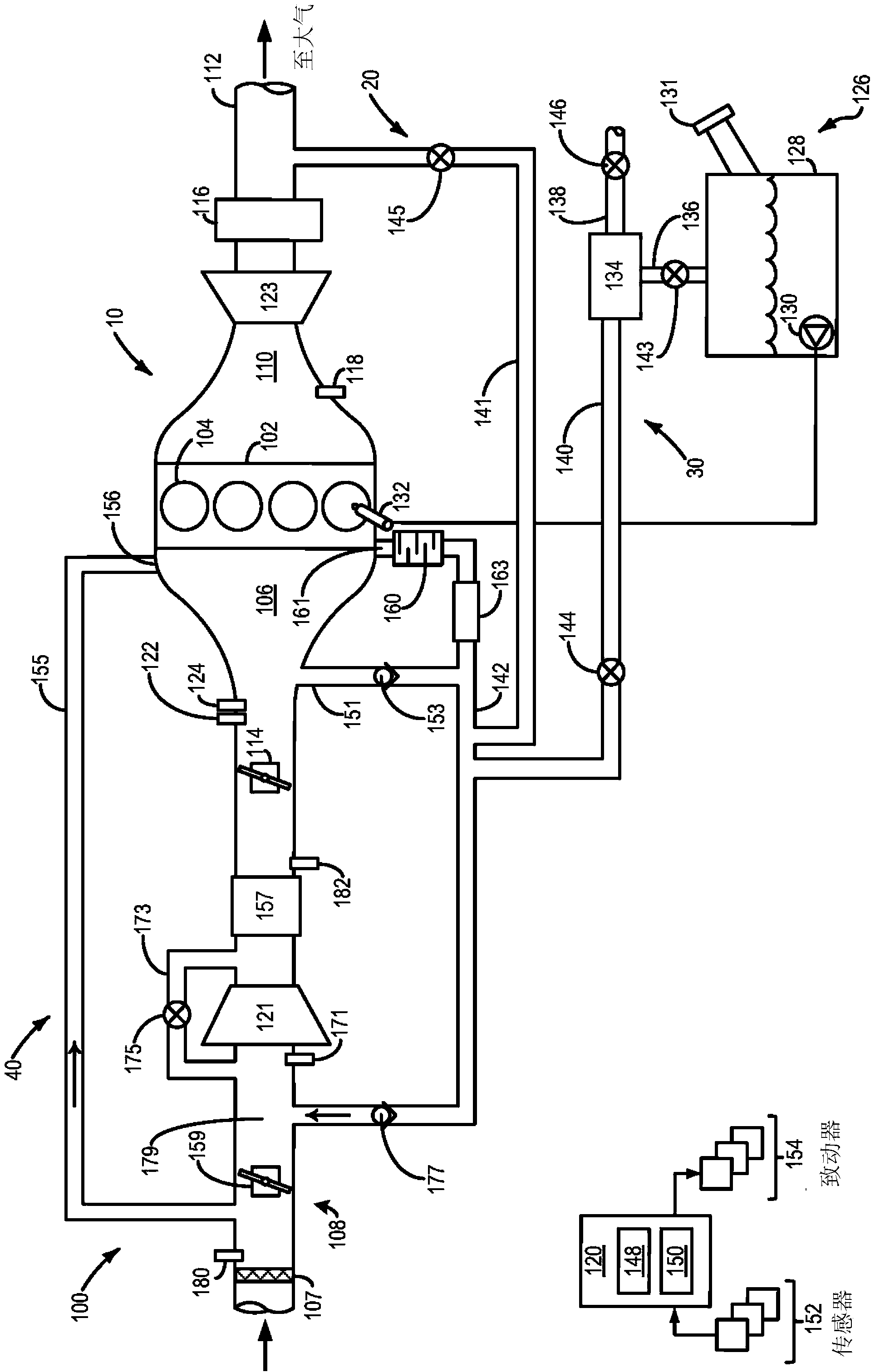
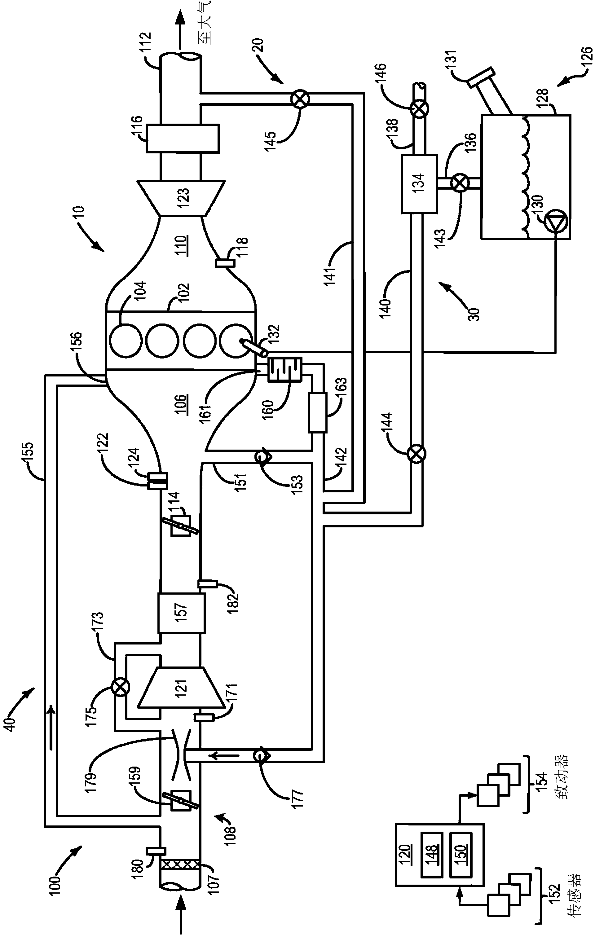
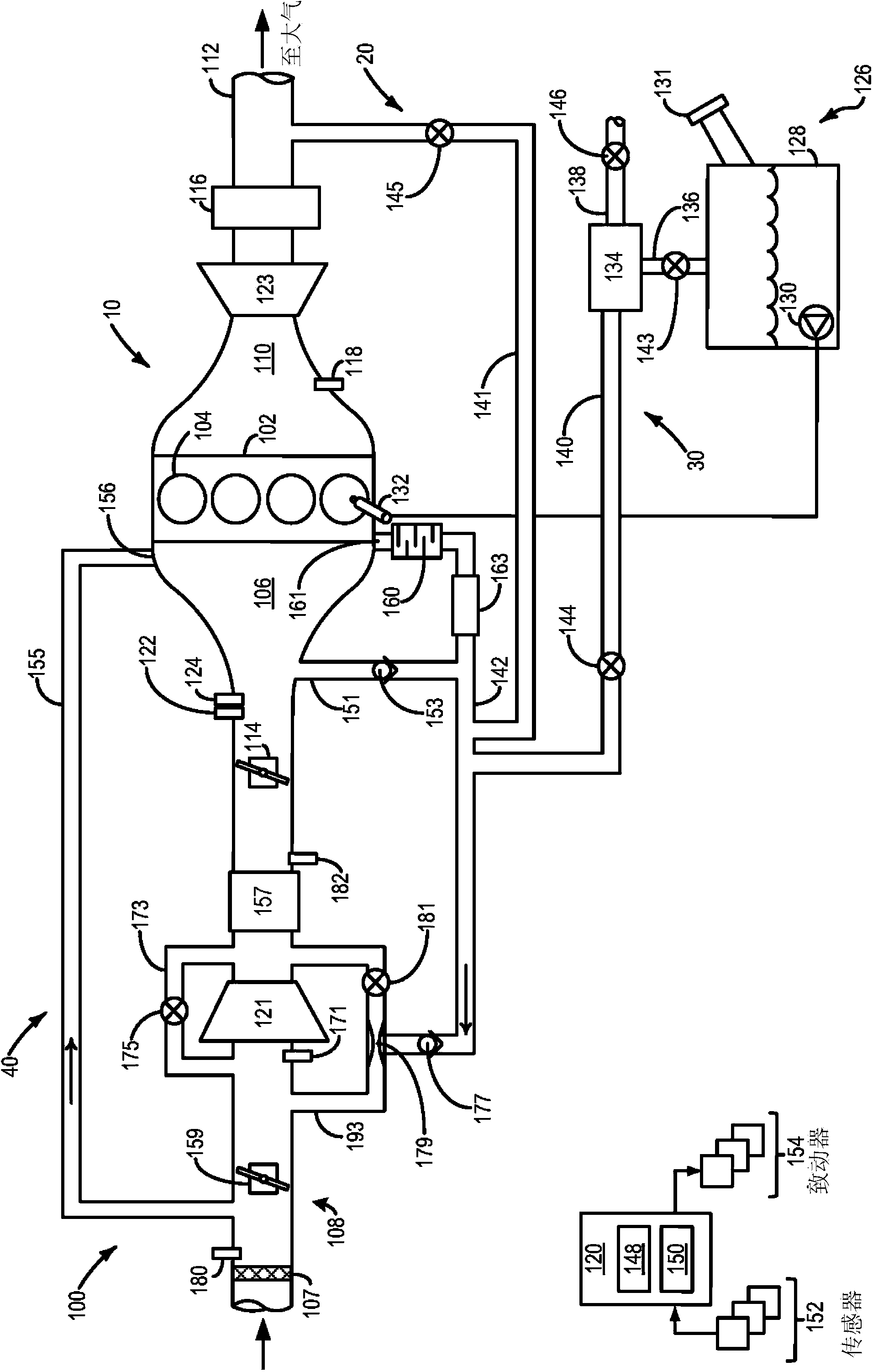
[0011] This detailed description relates to the Figure 1-4 Systems and methods for providing vacuum by one or more of a crankcase ventilation system, an emission control system, and an exhaust gas recirculation (EGR) system in an engine system shown in . like Figure 1-4 As shown, a vacuum source such as an ejector or a venturi can be included in the intake port of the engine downstream of the compressor pre-throttle and upstream of the intake throttle, and can be used to provide a vacuum proportional to the flow rate of the engine intake air. proportional vacuum. like Figure 5 As shown, the vacuum generated by the vacuum source in the engine intake may be used to drive consistent flow through crankcase ventilation systems, emission control systems, and exhaust gas recirculation (EGR) systems included in the engine system.

[0012] figure 1 An example of an engine system 100 according to an embodiment of the disclosure is schematically shown. Engine system 100 may be inc...


PUM


Abstract

Systems and methods for providing vacuum to one or more of a crankcase ventilation system, an emission control system, and an exhaust gas recirculation (EGR) system included in a turbocharged engine system are provided. In one example, approach, a method comprises drawing vacuum from a vacuum source located in an intake of the engine downstream of a pre-compressor throttle and upstream of an intake throttle, and applying the drawn vacuum to a discharge outlet of a uni-directional crankcase ventilation system, where an inlet of the crankcase ventilation system is coupled to the intake of the engine upstream of the pre-compressor throttle.

Description

technical field [0001] The present invention relates to a system and method for gas extraction control. Background technique [0002] The engine may direct various gas streams to an intake system, such as an evaporative emissions system, an exhaust gas recirculation (EGR) system, and / or a crankcase ventilation system. The vacuum generated in the intake system can be used to drive gas circulation through the aforementioned system. Valves may be used on the aforementioned systems to control the amount of gas entering the intake system. [0003] In some aspects, the vacuum used to drive the circulation of gases through the aforementioned systems may be based on engine intake manifold vacuum. For example, a crankcase ventilation system may rely on intake manifold vacuum to pull gas flow rates from the crankcase to force ventilate the crankcase. As another example, vacuum generated in the intake manifold may be used to purge fuel vapors stored in a fuel vapor canister of an ev...

Claims


Application Information

Patent Timeline
Patent Type & Authority Applications(China)
IPC IPC(8): F02B37/12F01M13/00F02M25/07
CPCF01M13/022F02M25/08F02M25/0712F01M2013/027F02D41/0007F02D41/003F02D41/0042F02D41/005F02D2250/41F02M25/089F02M26/06F02M26/07F02M26/10F02M26/19F02M26/36F02B37/162Y02T10/12Y02T10/40
Inventor R·D·珀西富尔
Owner FORD GLOBAL TECH LLC
Why Eureka
Try Eureka