
Vertical-axis wind power generation system working according to double-wind-turbine double-wind-speed power curves

A technology of wind power generation system and power curve, which is applied to wind turbines at right angles to the wind direction, wind turbines, and control of wind turbines, etc., can solve the problems of difficulty in implementation and narrow working wind speed range of wind power generation systems.

Inactive Publication Date: 2014-10-29
伍培云
View PDF0 Cites 5 Cited by
  • Summary
  • Abstract
  • Description
  • Claims
  • Application Information

AI Technical Summary

Problems solved by technology

[0003] According to Bates theory, wind energy utilization coefficient The limit value of the wind power generation system is 0.593, which is an upper limit, and any form of wind power generation system cannot break through this upper limit. To solve the problem of the narrow working wind speed range of the existing wind power generation system, especially in low wind speed areas, only by increasing (Like a variable pitch fan), it is difficult to achieve, so at low wind speeds, the area of ​​the wind rotor must be doubled , in order to increase the generating capacity of the generator

Method used


Image

  • Vertical-axis wind power generation system working according to double-wind-turbine double-wind-speed power curves
  • Vertical-axis wind power generation system working according to double-wind-turbine double-wind-speed power curves
  • Vertical-axis wind power generation system working according to double-wind-turbine double-wind-speed power curves

Examples


Embodiment Construction

[0015] specific implementation plan

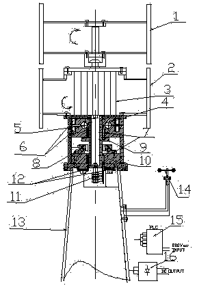
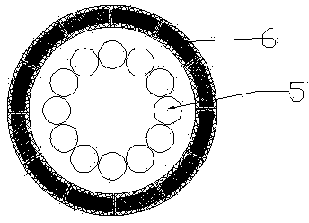
[0016] As shown in the attached figure, when the wind speed sensor (14) detects that the wind speed of the environment where the wind power generation system is located is greater than the predetermined starting wind speed of the fan (for example, the wind speed is 2 m / s), the PLC controller (15) will send The electromagnetic coil in the magnetic levitation device (6) is energized, and the polarity of the opposite magnetic poles in the gap of the magnetic levitation device (6) is the same, generating a repulsive force, so that the rotating body (4) fixed to the generator (3) is in the state of magnetic levitation, and the rotating body (4) There is no vertical contact with the connecting device (10) except for the cylindrical bearing (7) and the slip ring (11), and the resistance moment is very small. The central axis of the generator (3) rotates, and the wind torque of the rotor wind wheel (1) acts on the rotor to reversely rotate around ...


PUM


Abstract

The utility model discloses a vertical axis wind power generation system working on a double wind speed power curves. Two groups of Darrieus wind wheels are designed, one group of Darrieus wind wheel is arranged on a rotor of a generator and the other group of Darrieus wind wheel is arranged on a stator of the generator, however, rotating directions of the Darrieus wind wheels are just opposite. The bottom of the generator is fixed on a rotating body; the rotating body can freely rotate around a center axis of the generator in a magnetic suspension non-friction mode; at a low wind speed, double wind wheels work; at a high wind speed, only the rotor wind wheel works; according to variation of the wind speed, the wind power generation system is controlled to circulate the two working modes by a PLC (Programmable Logic Controller) and double-power-curve working of the system on the low-wind-speed power curve and the high-wind-speed power curve; and the start wind speed is low; and the working wind speed range is wide. The vertical axis wind power generation system is particularly suitable for vast areas with nonuniform annual wind speed distribution; and annual energy output can be improved severalfold. The wind power generation system disclosed by the utility model has reliable performance, is stable, has a simple structure, is easy to manufacture, is low in cost, is difficult to damage, is durable and is easy to maintain.

Description

technical field [0001] The invention belongs to a vertical axis wind power generation system. The system can realize the dual power curve work on the low wind speed power curve and the high wind speed power curve, and overcomes a disadvantage inherent in the existing wind power generation system. The working wind speed of the wind power generator The narrow range is the contradiction between low wind speed and high wind speed. However, the power generation system has the same power generation capacity at low wind speeds and high wind speeds, and reduces the starting wind speed and widens the working wind speed range of the generator. It is especially suitable for areas where the distribution of annual wind speed is very uneven, and the annual power generation can be increased several times. Background technique [0002] At present, there are many types of wind power generation systems on the market, including horizontal axis and vertical axis wind power generation systems. ...

Claims


Application Information

Patent Timeline
IPC IPC(8): F03D3/02F03D7/06
CPCY02E10/74Y02P70/50
Inventor 伍培云王洪福顾曙敏
Owner 伍培云
Learn More