heat pump system

A technology of a heat pump system and an outdoor heat exchanger, applied in the field of air conditioning, can solve the problems of reducing the life of the compressor and the system, increasing the maintenance and use costs, and the large size of the heat pump system, so as to improve the reliability of the system and improve the liquid hammer phenomenon. Effect

Active Publication Date: 2016-08-17
HEFEI MIDEA HEATING & VENTILATING EQUIP
View PDF7 Cites 0 Cited by
  • Summary
  • Abstract
  • Description
  • Claims
  • Application Information

AI Technical Summary

Problems solved by technology

However, this traditional heat pump system is prone to cause liquid shock of the compressor during defrosting operation, which will cause certain damage to the compressor and the system, reduce the life of the compressor and the system, and increase maintenance and use costs
Moreover, for a heat pump system with a large number of horsepower, a large-volume gas-liquid separator is often required, resulting in an excessively large overall volume of the heat pump system, and the separation effect is limited, and the safety of the system operation is poor.

Method used


Image

  • heat pump system

Examples


Embodiment Construction

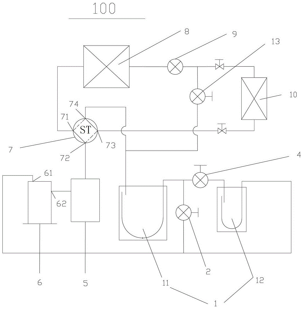
[0020] Embodiments of the present invention are described in detail below, examples of which are shown in the drawings, wherein the same or similar reference numerals designate the same or similar elements or elements having the same or similar functions throughout. The embodiments described below by referring to the figures are exemplary only for explaining the present invention and should not be construed as limiting the present invention.

[0021] In describing the present invention, it should be understood that the terms "center", "longitudinal", "transverse", "upper", "lower", "front", "rear", "left", "right", " The orientations or positional relationships indicated by "vertical", "horizontal", "top", "bottom", "inner" and "outer" are based on the orientations or positional relationships shown in the drawings, and are only for the convenience of describing the present invention and Simplified descriptions, rather than indicating or implying that the device or element refe...


PUM


Abstract

The invention discloses a heat pump system, which comprises a compressor, a four-way valve, an outdoor heat exchanger, an indoor heat exchanger, a gas-liquid separator, and first and second control valves. The exhaust port of the compressor is connected with the exhaust port of the four-way valve. The outdoor heat exchanger is connected with the outdoor heat exchanger interface of the four-way valve. The indoor heat exchanger is respectively connected with the outdoor heat exchanger and the indoor heat exchanger interface of the four-way valve. A plurality of gas-liquid separators are arranged in series, and the two on both sides are respectively connected with the suction port of the four-way valve and the suction port of the compressor. One end of each first control valve is connected to the suction port of the compressor, and the other end of each first control valve is connected to the one of any two adjacent gas-liquid separators that is closer to the suction port of the four-way valve The outlet of the gas-liquid separator is connected. Both ends of each second control valve are respectively connected with any two adjacent gas-liquid separators. The heat pump system of the invention realizes one-stage or multi-stage gas-liquid separation, improves the reliability of the system, and improves the liquid hammer phenomenon of the compressor.

Description

technical field [0001] The present invention relates to the technical field of air conditioning, in particular to a heat pump system. Background technique [0002] The traditional heat pump system has only one gas-liquid separator, and the refrigerant discharged from the four-way valve flows directly back to the compressor after passing through the gas-liquid separator. However, such a traditional heat pump system is likely to cause liquid shock of the compressor during defrosting operation, which will cause certain damage to the compressor and the system, reduce the life of the compressor and the system, and increase maintenance and use costs. Moreover, for a heat pump system with a large number of horses, a gas-liquid separator with a large volume is often required, resulting in an excessively large overall volume of the heat pump system, and the separation effect is limited, and the safety of the system operation is poor. Contents of the invention [0003] The present ...

Claims


Application Information

Patent Timeline
Patent Type & Authority Patents(China)
IPC IPC(8): F25B13/00F25B43/02
Inventor 张幸福
Owner HEFEI MIDEA HEATING & VENTILATING EQUIP
Why Eureka
Try Eureka