Speed reducing device for retrieving high-speed flight body with slight damage

A high-speed flying body and deceleration device technology, which is applied in the direction of warhead collectors, targets, offensive equipment, etc., can solve the problems of insufficient buffering of recycled objects, unfavorable secondary use of projectiles, and short contact buffer distance, etc., and achieves a simple structure , Reliable recovery, small deceleration displacement effect

Active Publication Date: 2014-10-29
ZHONGBEI UNIV
View PDF6 Cites 11 Cited by
  • Summary
  • Abstract
  • Description
  • Claims
  • Application Information

AI Technical Summary

Problems solved by technology

[0002] The existing projectile retractor for shooting targets under indoor conditions and the sensor recovery device for wide-pulse dynamic calibration of acceleration sensors have the common characteristics of adopting a hard recovery method for high-speed flying projectiles or sensors, and high-speed objects directly hit sand and soil, With high-density materi...

Method used


Image

  • Speed reducing device for retrieving high-speed flight body with slight damage
  • Speed reducing device for retrieving high-speed flight body with slight damage

Examples


Embodiment 1

[0017] Example 1. The deceleration device for micro-damage recovery of high-speed flying objects

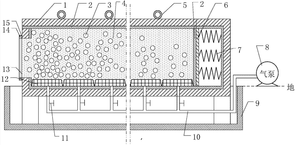
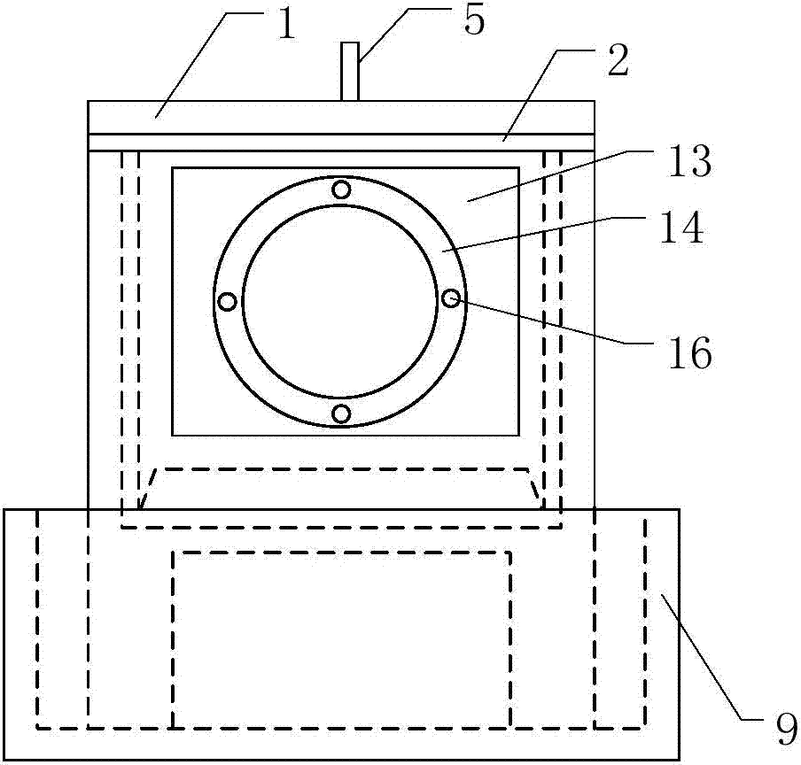
[0018] The deceleration device for micro-damage recovery of high-speed flying objects in this example is a deceleration device for micro-damage recovery of high-speed flying objects using non-isodensity air-water mixtures. The high-speed flying objects are at a speed of 50-500m / s Flying objects, the high-speed flying object in this example is an object flying at a speed of 500m / s. The meaning of the micro-damage is to make the high-speed flying body get a buffer of uniform deceleration during the recovery process, to ensure that the structure of the high-speed flying body is slightly damaged after being recovered, and to provide guarantee for the structural analysis and secondary utilization of the high-speed flying body. The specific structure of the deceleration device for recovering the high-speed flying body from the micro-damage of this example is as follows: Figure 1 ~ Fi...

Embodiment 2

[0019] Embodiment 2. The deceleration device for micro-damage recovery of high-speed flying objects

[0020] The specific structure of the deceleration device for recovering high-speed flying objects with micro-damage in this example can be Figure 1 ~ Figure 2 etc. have jointly shown that the deceleration device for micro-damage recovery high-speed flying objects in this example differs from the deceleration device for micro-damage recovery high-speed flying objects in Embodiment 1: 1. The high-speed flying object in this example is at a speed of 50m / s flying objects. 2. The wall of the recovery box in this example is made of rubber and high-strength stainless steel. The thickness of the rubber is 10mm, and the thickness of the stainless steel is 2mm. The length × width × height of the recovery box is: 4×0.3×0.3 m 3 . 3. the recycling box of this example faces the center position of the front wall of the high-speed flying body to open a circular hole whose diameter is sele...

Embodiment 3

[0021] Embodiment 3. The deceleration device for micro-damage recovery of high-speed flying objects

[0022] The specific structure of the deceleration device for recovering high-speed flying objects with micro-damage in this example can be Figure 1 ~ Figure 2 etc. have jointly shown that the deceleration device for micro-damage recovery of high-speed flying objects in this example is different from the deceleration devices for micro-damage recovery of high-speed flying objects in Embodiment 1 and Embodiment 2: 1. The high-speed flying objects in this example are based on 100m Objects flying at / s speed. 2. The wall of the recovery box in this example is made of rubber and high-strength stainless steel. The thickness of the rubber is 6mm, and the thickness of the stainless steel is 3mm. The length × width × height of the recovery box is: 5×0.4×0.4 m 3 . 3. the recycling box of this example opens a circular hole with a diameter of 150mm at the center of the front wall of th...


PUM

PropertyMeasurementUnit
Thicknessaaaaaaaaaa
Thicknessaaaaaaaaaa
Thicknessaaaaaaaaaa

Abstract

The invention discloses a speed reducing device for retrieving a high-speed flight body with slight damage, and belongs to the technical field of buffer protection. The speed reducing device is a speed reducing device for retrieving the high-speed flight body with slight damage through non-isopycnic air and water mixtures, and the flying speed of the high-speed flight body ranges from 50 m/s to 500 m/s. The speed reducing device is composed of a retrieval box, water, bubbles, a bubble generator, a felt pad, rubber, springs, a water pool and the like, wherein the water, the bubbles, the bubble generator, the felt pad, the rubber and the springs are arranged in the retrieval box, the retrieval box is placed into the water pool, the bubbles are generated by the bubble generator, a buffer and speed-reducing mechanism is formed by non-isopycnic air and water mixture space in the forwarding direction of the flight body from the edge of the front wall of the interior of the retrieval box, a retrieval protection mechanism is formed by the felt pad on the rear portion of the retrieval box, the rubber and the springs, and the water pool is used for recycling water which overflows after the high-speed flight body penetrates through film on an inlet of the retrieval box. The speed reducing device has the advantages that the non-isopycnic air and water mixtures are used for effectively buffering the high-speed flight body, the structure of the flight body is slightly damaged, it can be ensured that the speed of a high-speed flying object is evenly reduced under the condition of small acceleration, the speed reducing device has the advantages of being simple in structure, convenient to use and reliable in retrieval, and the speed reducing device for retrieving the high-speed flight body with slight damage is worthy of application and popularization.

Description

technical field [0001] The deceleration device for micro-damage recovery of high-speed flying objects disclosed by the invention belongs to the technical field of buffer protection, and specifically relates to a deceleration device for substantially uniformly decelerating high-speed flying objects to a stop under the premise of least damage. Background technique [0002] The existing projectile retractor for shooting targets under indoor conditions and the sensor recovery device for wide-pulse dynamic calibration of acceleration sensors have the common characteristics of adopting a hard recovery method for high-speed flying projectiles or sensors, and high-speed objects directly hit sand and soil, With high-density materials such as felt pads or wooden target boards, the contact buffer distance between high-speed flying objects and the deceleration structure is short, and a large acceleration impact is generated instantaneously. It is not conducive to the analysis of the str...

Claims


Application Information

Patent Timeline
IPC IPC(8): F41J13/00
Inventor 尤文斌丁永红马铁华黄慧祖静李新娥裴东兴范锦彪
Owner ZHONGBEI UNIV
Why Eureka
Try Eureka