Sand prevention hydraulic anchor

A hydraulic anchor and anchor claw technology, which is applied to wellbore/well components, earthwork drilling, etc., can solve the problems such as the failure of normal tripping of the operation pipe string, the overhaul of oil and water wells, and the tedious installation and use, so as to achieve low cost of use, Reliable recovery and simple installation

Inactive Publication Date: 2014-03-26
YANCHENG SENXIN PETROLEUM MACHINERY
View PDF0 Cites 4 Cited by
  • Summary
  • Abstract
  • Description
  • Claims
  • Application Information

AI Technical Summary

Problems solved by technology

However, due to the defects in the structural design of commonly used hydraulic anchors, the anchor fluke is fixed on the anchor fluke hole of the main body through a pressure plate and a solid screw, which solves the above problems to a certain extent, but due to its unreasonable structure, the installation and use are cumbersome. Low work efficiency and other problems, the recovery of the a

Method used


Image

  • Sand prevention hydraulic anchor

Examples


Example Embodiment

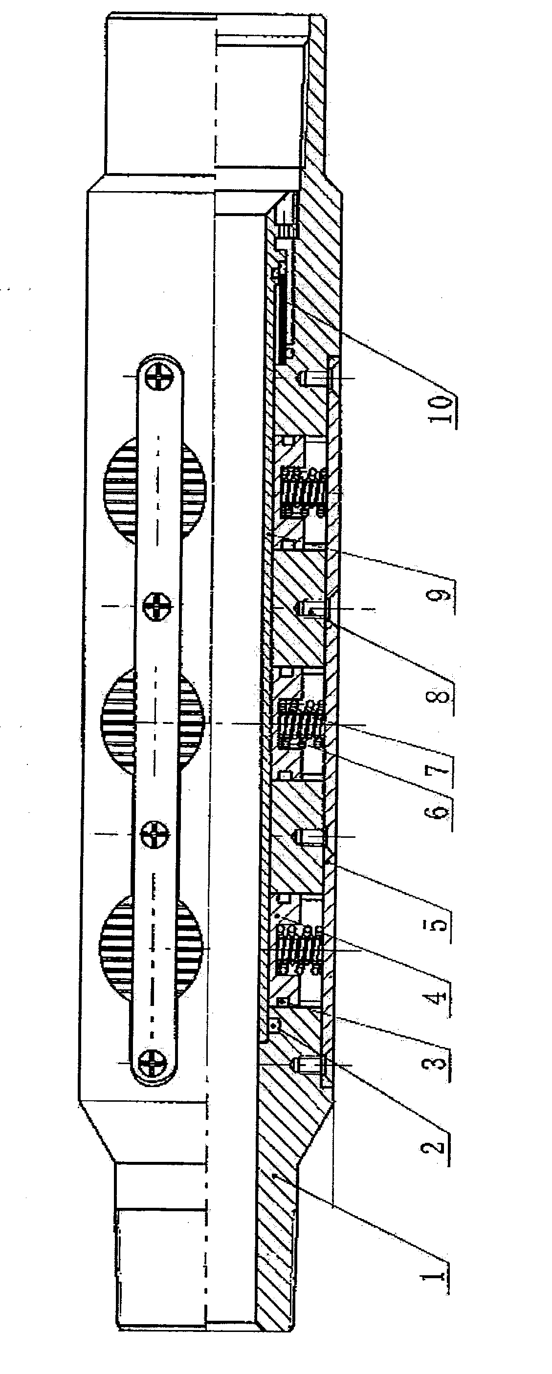
[0011] A sand-proof hydraulic anchor, including an anchor body 1, a sealing ring 2, a sealing ring A3, an anchor claw 4, a pressure plate 5, an outer spring 6, an inner spring 7, a pressure plate screw 8, a sand control intubation tube 9, and a sand filter screen 10, its features The anchor body 1 is provided with an inner seal groove and a pressure plate groove, there are three seal rings A3, three anchor flukes 4, four pressure plate screws 8, and the inner spring 7. There are three sets of outer springs 6 respectively. Insert the sealing ring 2 into the inner sealing groove of the anchor body 1, set the sand filter screen 10 on the outer cylindrical surface of the sand control intubation tube 9, and then connect it through the inner thread of the anchor body 1. Tighten. The fluke 4 is provided with an outer sealing groove, and the sealing ring A3 is respectively embedded in the outer sealing groove of the fluke 4, and the inner spring 7 and the outer spring 6 are placed in ...


PUM


Abstract

A sand prevention hydraulic anchor comprises an anchor body, a sealing ring, a sealing ring A, an anchor jaw, a press plate, an outer spring, an inner spring, a press plate screw, a sand prevention insertion pipe and a sand filtering screen. The sealing ring is embedded into an inner sealing groove of the anchor body, and the sand filtering screen is sleeved on the outer cylindrical face of the sand prevention insertion pipe and is screwed through inner threads in the anchor body. An outer sealing groove is formed in the anchor jaw, the sealing ring A is embedded into the outer sealing groove of the anchor jaw, an inner spring and an outer spring are sequentially arranged in an inner hole of the anchor jaw, the anchor jaw is installed in the hole of the anchor jaw along the axial direction of the anchor body, and the press plate is pressed in a press plate groove of the anchor body to prevent the anchor jaw from stretching out and is fixed through the press plate screw. When hydraulic pressure is added from the inside of an oil pipe, the anchor jaw compresses the springs under the hydraulic pressure effect and is pushed to the inner wall of the sleeve and clamped firmly on the inner wall of the sleeve to achieve the aim of fixing a pipe column. When the pressure in the oil pipe is released, the anchor jaw retreats under the effect of the springs, and clamping is released. The hydraulic anchor is reasonable in structure design, simple and convenient to install and saves production cost.

Description

technical field [0001] The invention belongs to oil field equipment, and relates to an anchoring device for downhole pipe strings, in particular to a sand control hydraulic anchor for oil and gas field production. Background technique [0002] As the oilfield enters the later stage of development, the number of hard-to-recover blocks increases, the water injection pressure is high, and the technical conditions of downhole strings for layered water injection and layered squeeze injection are relatively complicated. At present, layered water injection packers are widely used in oilfields. Ground tests have proved that when the pressure fluctuates in the range of 5-25MPa, that is, the packer creeps 4-5 times, and the rubber cartridge of the packer will fail, which seriously affects the normal operation of the oilfield. Production. In order to solve the creeping problem of the water injection string, the hydraulic anchor, as a downhole string anchoring device, is often used in ...

Claims


Application Information

Patent Timeline
IPC IPC(8): E21B23/04
Inventor 徐红军徐丰岭
Owner YANCHENG SENXIN PETROLEUM MACHINERY
Why Eureka
Try Eureka