
Shipborne unmanned aerial vehicle recovery docking window motion simulation device and method

A motion simulation and unmanned aerial vehicle technology, which is applied in the direction of parking devices, ground devices, transportation and packaging, etc., can solve the problems of incompletely resolved risks of dynamic docking, and achieve the effect of simple structure, easy implementation, and risk reduction

Active Publication Date: 2021-11-19
CHINA SHIP DEV & DESIGN CENT
View PDF6 Cites 4 Cited by
  • Summary
  • Abstract
  • Description
  • Claims
  • Application Information

AI Technical Summary

Problems solved by technology

[0002] Chinese patent "a fixed-wing unmanned aerial vehicle short-distance common rail launch and recovery device", patent authorization number: ZL201710731451.6 discloses a short-distance launch And the proprietary technology and device concept scheme for recovering fixed-wing UAVs. This patent is based on gas-hydraulic composite power and an 8-fold ratio of pulley ropes on a track with a length of about 10m to achieve a short-distance fixed-wing UAV. The common rail launch and recovery function, this principle has been verified by the model machine recovery test to verify the rationality of the power system, but the risk of dynamic docking in the swing environment has not been completely resolved, it is necessary to develop a relatively safe dynamic docking method, Not only to verify whether the accuracy of the guidance system meets the requirements, but also to verify the success rate of UAV simulated docking under the recovery "window" movement condition, and based on this, formulate UAV recovery and go-around strategies to guide the real machine recovery Workflow formulation

Method used


Image

  • Shipborne unmanned aerial vehicle recovery docking window motion simulation device and method

Examples


Embodiment Construction

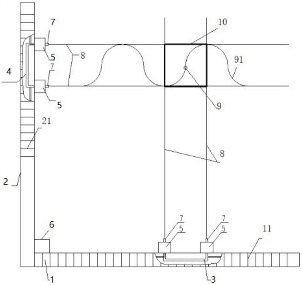
[0027] now attached figure 1 The motion simulation device and method for the docking window recovery of shipborne UAV implemented according to the present invention will be described to verify the effect of the present invention on the compound guidance accuracy of UAV. The present invention is not limited to the following embodiments.

[0028] The ship-borne unmanned aerial vehicle recovery docking window motion simulation device of the present invention comprises a horizontal translation slide rail 1, a longitudinal translation slide rail 2, four moving pulleys 5 (two horizontal moving pulleys 5, two longitudinal moving pulleys 5), a lateral movement A servo actuator 3, a longitudinal motion servo actuator 4, four high-power laser sources 7 mounted on a moving trolley 5, a signal transmission base station 6, and a power system that provides power for the servo actuator.

[0029] The horizontal translation slide rail 1 and the vertical translation slide rail 2 are vertically ...


PUM


Abstract

The invention discloses a ship-borne unmanned aerial vehicle recovery docking window motion simulation device and method. The device comprises a transverse translation sliding rail and a longitudinal translation sliding rail which are arranged perpendicular to each other, wherein the transverse translation sliding rail and the longitudinal translation sliding rail are respectively provided with two moving pulleys which move synchronously and keep a distance, the moving pulleys are provided with high-power laser sources used for generating rays, two transverse rays and two longitudinal rays intersect in an emission state, a butt joint window which moves according to a regular curve is generated at the intersection, the center point of a docking window is set as a target point for unmanned aerial vehicle recovery docking; and a signal sending base station receives the central position of the docking window and transmits the position to the unmanned aerial vehicle in real time. A track of a recovery window changing along with ship motion can be simulated on the land, the center point information is fed back to the unmanned aerial vehicle, and the unmanned aerial vehicle is guided to continuously approach an ideal cable hanging point, so safe and reliable recovery is realized, and a real vehicle offshore docking risk is eliminated in advance.

Description

technical field [0001] The invention belongs to the field of ship-borne aviation support equipment, and specifically relates to an aviation simulation device and method, which are used to simulate on land the change of the recovery window of the launch recovery device as the ship moves in the air, so as to resolve the risk of docking and recovery of the real aircraft at sea. Background technique [0002] Chinese patent "A device for short-distance common-rail launch and recovery of fixed-wing unmanned aerial vehicles", patent authorization number: ZL201710731451.6 discloses a proprietary technology and device concept for short-distance launch and recovery of fixed-wing unmanned aerial vehicles , the patent realizes the short-distance common-rail launch and recovery functions of fixed-wing UAVs on a track about 10m long based on gas-hydraulic compound power and 8-fold ratio pulley ropes. This principle has passed the model machine recovery test The rationality of the power sy...

Claims


Application Information

Patent Timeline
Patent Type & Authority Applications(China)
IPC IPC(8): B64F1/02B64F5/00
CPCB64F1/02B64F5/00Y02P70/50
Inventor 娄相芽胡哲王云吴其俊何俊
Owner CHINA SHIP DEV & DESIGN CENT
Learn More