Parts mounting apparatus and parts mounting method and waste materials recovering apparatus

A recovery device and parts installation technology, which is applied in the field of parts installation, can solve problems such as increased configuration of the rotating drive device, longer stop time, and obstacles to high-speed speed, and achieve the effects of preventing bad situations, eliminating contact states, and improving quality

Inactive Publication Date: 2004-04-07
PANASONIC CORP
View PDF3 Cites 4 Cited by
  • Summary
  • Abstract
  • Description
  • Claims
  • Application Information

AI Technical Summary

Problems solved by technology

However, at this time, since the roller 134 moves in two directions, the vertical direction H1 along the guide groove 160 and the circumferential direction H2 along the cam surface 141 of the cylindrical cam portion 140, neither of them will come into rotational contact. And become the contact state with sliding, on roller 134, cam surface 141 and the groove side surface of guide groove 160 etc., abrasion occurs, and the part that wears can produce rattling.
[0033] further, such as Figure 27 As shown, although there is a mechanism for selecting the nozzle 170 by setting a rotating drive device at a position away from the suction nozzle, in this mechanism, when selecting the nozzle 170, in order to cooperate with the gear 171 through the matching rod 172, Disengaged, and the gear 171 is rotated by the rotary drive device at a position away from the suction nozzle, so that the nozzle 170 is selected, the configuration of the external rotary drive device will be increased, and the time to stop will be longer, so it becomes a high speed. barriers to

Method used


Image

  • Parts mounting apparatus and parts mounting method and waste materials recovering apparatus
  • Parts mounting apparatus and parts mounting method and waste materials recovering apparatus
  • Parts mounting apparatus and parts mounting method and waste materials recovering apparatus

Examples


Embodiment Construction

[0083] A waste material recycling apparatus according to a first embodiment of the present invention will be described below with reference to the drawings. In addition, in each of the following embodiments, the same reference numerals are used for the same constituent elements as those of the prior art, and in each of the following descriptions, differences from the prior art will be mainly described.

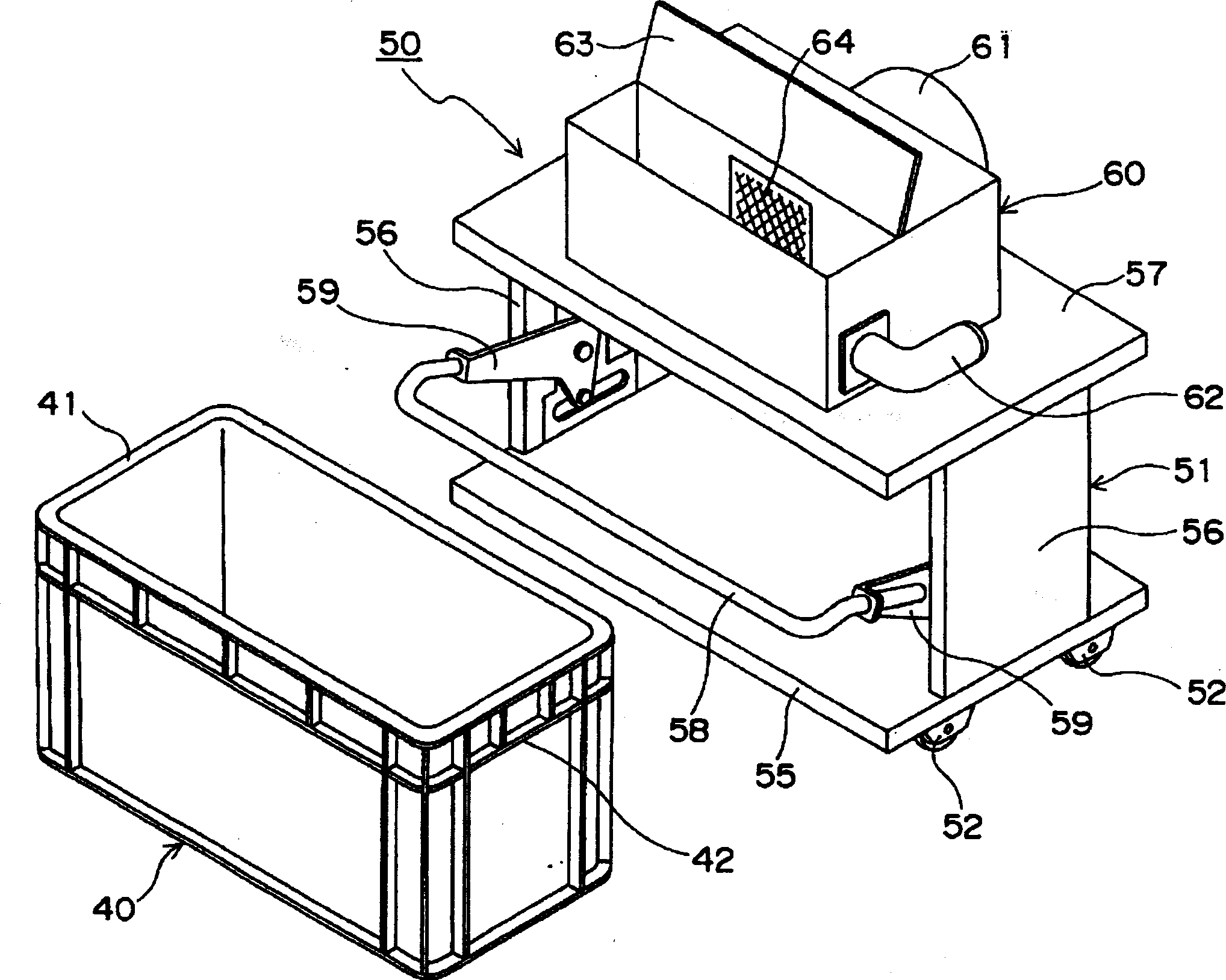
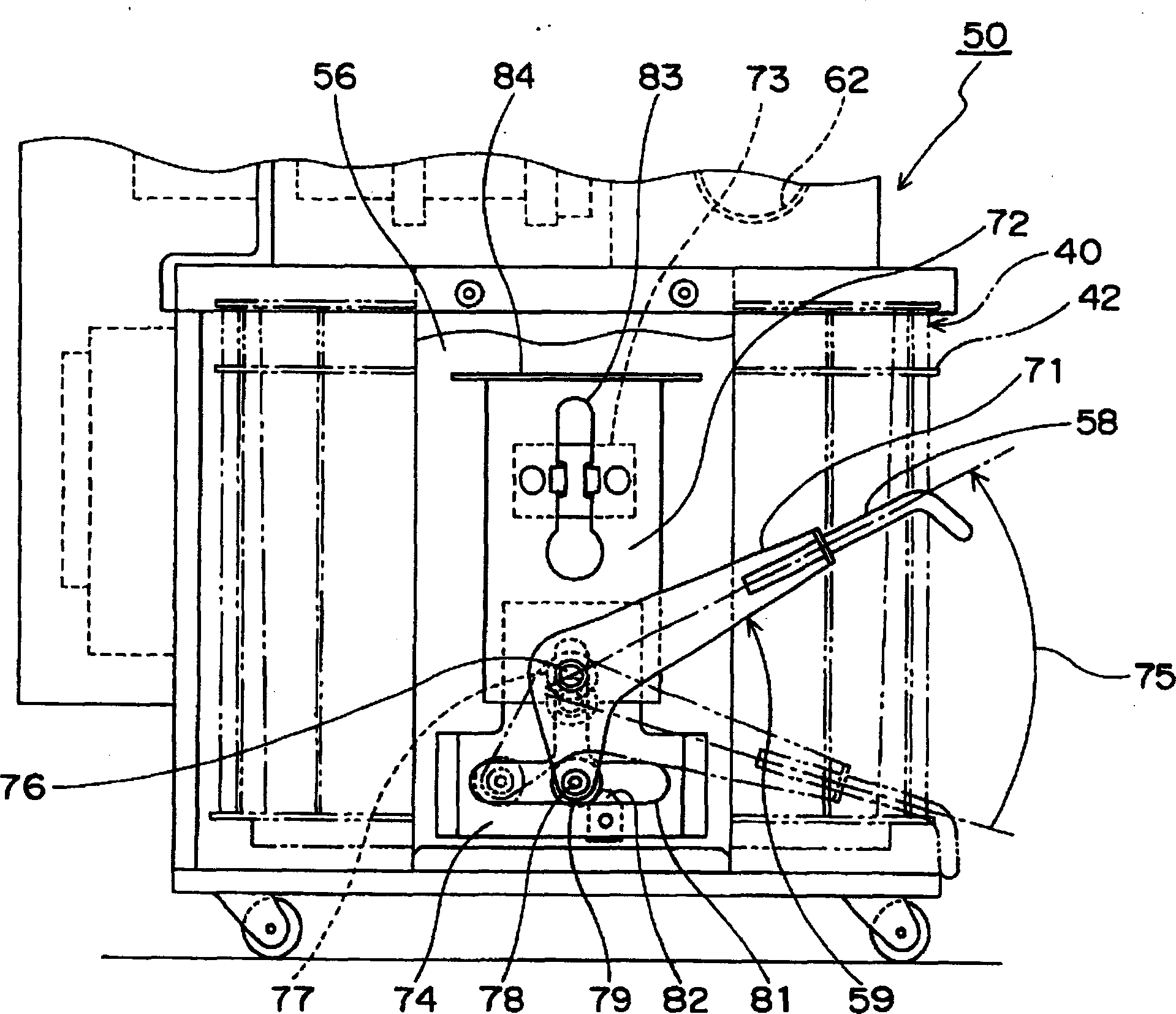
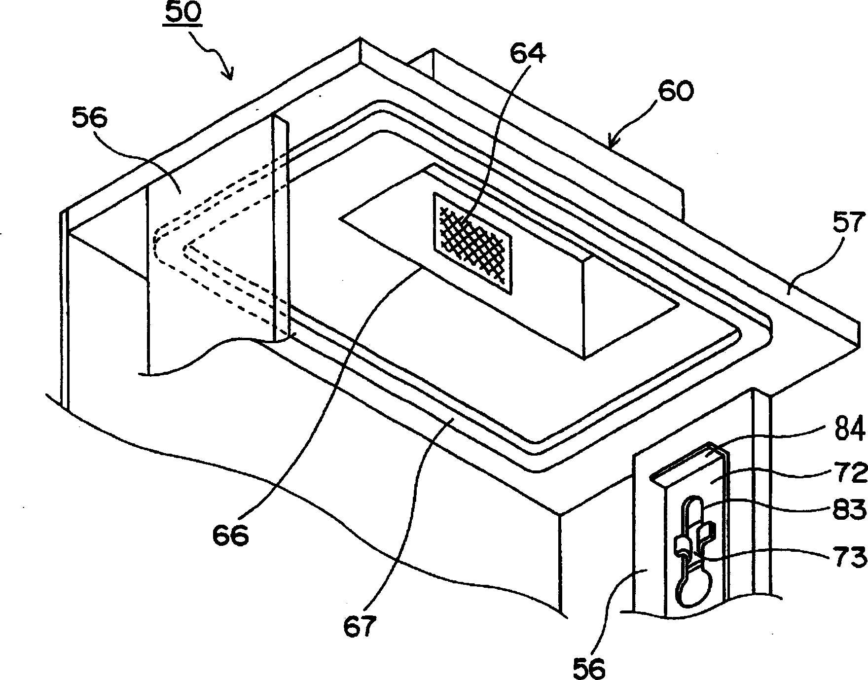
[0084] figure 1Indicates the waste material recycling apparatus related to this embodiment. This waste material recovery device can be used, for example, to recover tape scraps generated after cutting the parts supply tape after the parts supply is completed. In the figure, the waste material recycling device 50 of this embodiment mainly includes: a frame portion 51 of a peripheral frame composed of a lower frame body 55, a pair of side frame bodies 56, and an upper frame body 57; The negative pressure suction unit 60 for sucking waste materials from the component mounting ...


PUM


Abstract

To provide a component mounting apparatus which has a simple structure and therefore can reduce a manufacturing cost, and has no probability of causing problems caused by rattling by abrasion. The component mounting apparatus comprises a plurality of chucking nozzles 30, a rod 26, a motor 22 for rotating the rod 26, and a cylindrical cam 40. Each of the chucking nozzles 30 has such a structure that first and second rollers 33 and 34 are attached to a support pin 32 projecting on the peripheral surface of a body 31 of a chucking nozzle. The rod 26 holds the chucking nozzles 30 so that they can move vertically, and are formed with vertically arranged guide grooves 35, with side faces of which the first rollers 33 are brought into contact. The cylindrical cam 40 has its cam surfaces 41 in contact with the second rollers 34, and makes relative rotation between the second roller 34 and the rod 26 to control heights of the chucking nozzles 30. At the rotation of the rod 26, the second rollers 34 roll and move on the cam surfaces 41 of the cylindrical cam 40, while the first rollers 33 roll and move on the side faces of the guide grooves 35, resulting in locating the chucking nozzles 30 used for mounting components at a lowest position. (C)2004,JPO.

Description

technical field [0001] The present invention relates to a component mounting device and a component mounting method for mounting components such as electronic components on a circuit board. More specifically, the present invention relates to a waste that collects waste materials such as used parts supply tape discharged after supplying parts to a parts mounting device, and discarded parts that have not been mounted in the parts mounting device. A material recovery device, a parts mounting device having the waste parts recovery device, and a parts mounting method for recovering waste parts by suction. The present invention also relates to a component mounting device having a rotatable rotary head in which a plurality of component mounting jaws are radially arranged. Background technique [0002] In order to continuously supply various types of components that are consumed in large quantities to the component mounting device as the speed of the component mounting device has i...

Claims


Application Information

Patent Timeline
Patent Type & Authority Applications(China)
IPC IPC(8): B09B3/00
CPCY02W30/82
Inventor 长泽阳介今野宏则今川宏明纐缬尚人藤崎邦夫平井弥中岛诚
Owner PANASONIC CORP
Why Eureka
Try Eureka